
Datasheet

PmodENC™ Reference Manual
Copyright Digilent, Inc. All rights reserved.
Other product and company names mentioned may be trademarks of their respective owners.
Page 2 of 3
The two internal buttons are both natively pulled to a logic high level through a pull-up resistor. As the two buttons
are located 90 degrees from each other (i.e. in quadrature), while the shaft is rotating one button will be pulled to
a low logic level voltage before the other button.
Figure 1. Rotary shaft encoder circuitry.
Users can program their system boards to determine which button was pulled low last (within a small time frame
to ensure additional “clicks” are not also captured) in order to figure out which direction the shaft is being rotated.
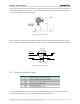
Switch Chatter
Rising edge of A first, then B
is decoded as a rotate right
Detent
A
B
Rotate Right
Figure 2. Timing of outputs A and B.
2.1 Pinout Description Table
Pin
Signal
Description
1
A
Output of button A in the encoder shaft
2
B
Output of button B in the encoder shaft
3
BTN
Output of the integral push button in the encoder shaft
4
SWT
Output of the on board switch
5
GND
Power Supply Ground
6
VCC
Positive Power Supply (3.3/5V)
It is recommended that Pmod is operated at 3.3V or 5V, although because there are no integrated circuits on the
Pmod, any voltage that your system board can handle as a digital input will work fine.