INSTALLATION GUIDE Ref. : 1871184 - 0107103 ASCARI MA12 ELECTRIC HEATING BOILER Ascari MA12 -p.
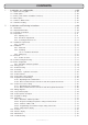
CONTENTS 1 - Installation ans configuration .................................................................................... p. 03 1.1 - Quick reference guide ................................................................................................................ p. 03 1.2 - Install options ............................................................................................................................. p. 04 1.3 - Boiler (serial numbers of 0500151 and over) .........................
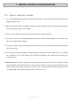
1 - INSTALLATION & CONFIGURATION 1.1 - Quick reference Guide 1. It is recommended that the boiler be connected to a 10hour or similar off-peak tariff that provides some daytime off-peak hours. 2. Where the off-peak tariff is restricted a changeover relay should be used to switch power to the boiler when the off-peak supply is not available. 3. Fill the system with water prior to turning on the electrical supply to the boiler. 4.
1.2 - Install Options 1. SPACE HEATING ONLY (recommended)-direct room thermostat Connection • The no-volt contacts of the room thermostat should be connected to terminals 1 and 2 of the boiler. • Menu option 4 should be set to 01 to allow the boiler to be controlled from the room thermostat. 2.
1.3 - Boiler (serial numbers of 0500151 and over) Two options are available: Option 1 - Operating from a Switched Live Switched Live 1. The switched live from the 10-way connector block should be connected to terminal 25, which is located beside the relay located in top right of the boiler. 2. In the set-up menu, set option 04 to 1 3. Auto-adaptability (option 6 of the set-up menu) should be turned off. 4.
1.4 - Menu Options The set-up menu should be configured as follows, some of these parameters will be modified by instructions in the previous sections.
1.5 - Summer / Winter Mode The right-hand snow flake symbol should be illuminated indicating winter mode. If the sunshine symbol is illuminated, select winter mode by pressure and holding the radiator button on the boiler for 3 seconds. In Summer mode the heating circuit is switched off but hot water, if installed will be still be heated. 1.6 - Underfloor Heating • For underfloor heating the 60oC internal temperature cut-out should be selected.
Ascari MA12 -p.
2 - INSTALLATION & DEVICING INSTRUCTIONS Features • Selectable Water Temperature - radiators/ Underfloor (21-80oC) • 60oC or 100oC thermal cut-out suitable for underfloor heating or radiators • Room Thermostat operation • Frost Protection, 5oC minimum temperature • Pump protection - once a day operation when system is off • Pump overrun facility • 4-stage stepped turn on/off • Weekly alternative switch start-up for prolonged life • Automatic water temperature variation for 50% on-off cycles (with room therm
2.2 - Important Information • The information given in this booklet is a guide only. All installations must follow the current regulations for this type of device and where no information or conflicting information is given in this guide to that of the current regulations, the current regulations will apply. • Disconnect the Electricity Supply before attempting to remove the cover of the boiler. • The boiler weighs 38kg and requires two persons to lift and install the product.
• A drain cock should be installed at the lowest point in the heating system to allow the water in the heating system to be drained as fully as possible. • While the boiler and heating system may be filled from the cold mains water supply, the boiler must be isolated from the cold mains water supply by a suitable break in the supply pipe during normal operation. • Filling Loop- this boiler is not fitted with a filling loop.
MECHANICAL Weight 38kg Dimensions 620mm h x 405mm w x 280 d Rating IPX1 Storage capacity 5 litres Connections 1"( 26/34) female Heat Exchanger Cast Iron Elements 2 heaters comprising 3 x 2kw incoloy elements Expansion Vessel 8 litres Pump 3-speed manually selectable Thermal cut-outs 2 units manually selectable 60oC or 100oC 2.4 - Preparation 2.4.1 - Opening Case The boiler may be opened by unscrewing the bottom two bolts a couple of turns (they do not need to be removed completely).
2.4.2 - Electrical Compartment With the cover removed access to the electrical connections is achieved by undoing the screw of the electric box. Once opened access is gained to the electrical connectors, for easy installation. 2.4.3 - Selecting Thermal cut-out The thermal cut-outs are situated at the top of the boiler and may be selected during the installation by rerouting the electrical connections. The boiler is factory set with the 100oC cut-out selected for use with radiator heating systems.
2.5 - Installation Requirements 2.5.1 - Location • The boiler must be located at least 300mm above any object to allow the elements to be removed. At least 100mm is required at the top of the boiler to allow for connection of pipework. • 10mm is required at the sides of the unit. • 100 10 10 The boiler must be mounted on an internal solid masonry wall capable of withstanding the weight of the product when full of water.
2.6.2 - Plumbing 2.6.2.1 - Radiators / Underfloor Room thermostat Air bleeders Service valves Radiators OR Pump Under Floor safety limiter if used with hot water cylinder Expansion Relief Valve Drain tap Expansion vessel Underfloor heating • Install the heating system bringing the flow and returns to the boiler location. • The system should be flushed prior to connecting the boiler to remove all particles from the pipework.
• A filling loop must be installed that isolates from the cold mains water supply from the heating system and complies with the current building and water regulations in force at the time. • The boiler incorporates an 8-litre expansion vessel which is suitable for heating systems as follows: Initial System Pressure (bar) Total Water in heating system (litres) For larger systems Multiply the volume of water by these factors 0,50 0,75 1,00 1,50 96 84 73 50 0,0833 0,0930 0,1090 0,1560 2.6.
2.7 - Electrical • Wiring external to the appliance must be in accordance with the current I.E.E Wiring regulations (BS 7671) for electrical installation and any local regulations, which apply. • With the boiler plumbed in, the electrical connections can be made to the boiler: • This appliance must be earthed! • The Ascari boiler comes with cage-clamp connectors. These are operated using a 2.5mm x 0.4mm blade screwdriver for accessory terminals and 3.5mm x 0.5mm blade screwdriver for power terminals.
2.7.1 Power selection The boiler is supplied as a 12Kw modulating boiler but can be reduced to 10, 8, 6 or 4kw by disconnecting individual elements. R Bl W B B B R Bl W R Bl W B B B B B 12 kW R Bl W B B B 10 kW* ex-work R Bl W B B R Bl W R Bl W B B B 8 kW* R Bl W B R Bl W B B 6 kW* R Bl W R Bl W B B 4 kW* : : : : Red Black White Blue View from bellow * Remove blue connectors between power terminal and elements according to drawing. 2.
• Refill the system from the filling loop, to a pressure between 1-1.5bar (0.1-0.15MPa) and operate the pressure relief valve manually to check that water runs away correctly, and that the valve closes correctly. • Top up the system to 1.0bar (0.1MPa). • Disconnect the system from the filling loop. • Check the electric connections and that all covers etc. have been replaced. Turn on the electricity supply to the boiler and allow the unit to do its self diagnosis. Refer to § 2.24 if a fault is displayed.
2.9.1 Automatic/ Manual Operation The boiler must be set to Manual operation as follows: Press and hold the Auto/Man button for 3 seconds. The display will show Au or Man, press the Auto/Man button again for a short period to toggle the display so that it shows Man. With the correct display showing, press and hold Auto/Man for 3 seconds to return to normal operating mode. 2.
2.
2.14 - Power terminal Put the self-sealing nut (supplied with the boiler) for connection to mains from the bottom of the casing. Put the self-sealing nut (supplied with the boiler) for connection to mains from the top of the casing. In this case remove the plastic cap and close the hole below casing using same.
2.15 - Connection to the electricity supply Ground 16² I: 63A fused supply on the consumer unit Neutral 16² via a double pole limited switch with minimum contact gap of 3mm. Phase 16² I NOTE : Stripped length of wires between 16 and 17mm Ascari MA12 -p.
2.16 - Regulation circuit drawing 2.16.1 - Operating from a switched live Decoding : L1 : Live N : Neutral F : 4A fuse size 5 x 20 K1 to K4 : 20A power breakers C1 : Electronic card with display DT : Total cut-out (remove the bridge) CC : 3 speed pump DP1 & DP2 : Partial cut-out (remove the SC : Boiler's sensor AQS1 : 60°C safety limitator with manual reset AQS2 : 100°C safety limitator with manual reset bridge) R Ascari MA12 -p.
2.16.
2.17 - Control accessories wiring 2.17.1 - Operating from a switched live 1-2 : External command relay contact 3-4 : n/a 5-6 : n/a 10 - 11 : Total cut-out DT (remove the bridge) and / or 65°C heating floor safety limitator (mandatory) with manual reset. See § 1.3.1.
2.17.2 - Direct room thermostat connections and direct cylinder thermostat 1-2 : Direct room thermostat connections 3-4 : n/a 5-6 : The brown wires should be removed from terminals 1 and 2 and be placed into terminals 5 ans 6 respectively 10 - 11 : Total cut-out DT (remove the bridge) and / or 65°C heating floor safety limitator (mandatory) with manual reset. See § 1.3.1.
2.18 - Wiring diagrams 3 OUT 4 pink pink grey grey yellow GND OUT pressure sensor connect. black red yellow white +Vdc 230 V / 12 V adaptator Outside sensor (S.Ext) DHW sensor white SC white boiler's sensor (SC) brown ambience thermostat (TA) brown orange black red red black white 230V power +Vdc 2 white pres sure sen sor powe grey r DHW pump C.
black red L1 External command L1 L2 A2 A1 L3 L4 black white L1 L2 T3 T4 A1 T4 A2 L3 red L4 A1 T2 T1 T3 T4 A2 blue black T1 balck red A2 red T2 T3 K3 blue T1 T2 T1 white T4 blue L2 T3 white L1 T2 L4 L3 K4 K1 blue black A1 red R 25 a2 balck a1 red brown brown 12 14 11 L4 K2 T1 red L3 L2 T2 bleu bleu Légende : AQS1 : 60°C Safety limitor with manual reset K1 to K4 : 20A power breakers AQS2 : 100°C safety limitor with manual reset T1 & T2 :
2.19 - 3 Speed water pump III II I 3 speed (I, II et III) water pump for adjustment to operating needs, depending on insulation and circuit The boiler is factory set at pump speed 3, for lower pump speeds the selector in the centre of the pump may be turned to 1 or 2 using a large flat bladed screwdriver. Electric datas Speed Nominal output (W) Nominal intensity (A) III 90 0,40 II 67 0,30 I 47 0,20 Ascari MA12 -p.
2.20 - Control pannel description Usual operating functions Boiler's temperature display in °C. When the boiler is off and the two middle horizontal LEDs on, antifrost protection is operating.
2.21 - Regulation settings For fitter's use only. The regulation must be adjusted according the use of the boiler. • Press and • Parameter # • Press or (3 sec) to start setting menu for 4 minutes. starts blinking in front of "°C" (instant touch) to select next parameter, i.e • To start setting the displayed parameter press • The parameter value, i.e or °C, ... until (instant touch). starts blinking in front of "bar". • Press or (instant touch) to change setting.
PARAMETERS LISTING Press and during 3 sec to access parameters menu.
2.22 - Operating Display in front of symbol "°C" means the boiler is off, connected to power supply, with anti frost protection operating (boiler starts automatically when the boiler's temperature or the Domestic Hot Water temperature turns below 5°C). Press to turn the boiler On or Off. 2.22.1 - Automatic / Manual Operation The boiler must be set to Manual operation as follows : Press and hold the Auto/Man button for 3 seconds.
2.22.4 - Programming the maximum output setting of the boiler The boiler is delivered with a maximum output of 12kW (parameter Set the parameter Set parameters of output of the boiler : = 1).
2.23 - Counters The regulation is equiped with 6 counters to count heating cycles (the unit is 100 cycles). Press and during 3 sec. The setting menu starts (see § 6.3). Press during 3 sec. : °C will be on display for counter #1, alternating with °C and bar, meaning power breaker #1 K1 is totalling more than 0999 x 100 = 99.900 cycles. Press to shift to counter #2. Conversely press to return to previous counter.
2.25 - Maintenance Once a year we recommend to have the boiler checked by a qualified technician. - Pressure inside the heating circuit needs to be controlled a a regular basis (pressure when cold will have to remain over 1 bar). - Frist a few days after cut-over, later at least once a year, check electric connections tightness of the heating elements and power supply. 2.
Fastening the pump If the pump is producing some abnormal noise, slightly unscrew without creating leackage, then screw again following instructions below. 1 - screw two opposite screws with a stroke of 3 Nm. 2 - screw the other two opposite screws with a stroke of 3 Nm 3 - screw the first two opposite screws with a stroke of 5 Nm. 4 - screw the last two opposite screws with a stroke of 5 Nm.
NOTE Ascari MA12 -p.
Ascari MA12 -p.