Installation Guide Model BFSL33 IMPORTANT SAFETY INFORMATION: Always read this manual first before attempting to install or use this fireplace. For your safety, always comply with all warnings and safety instructions contained in this manual to prevent personal injury or property damage. To view the full line of Dimplex products, please visit www.dimplex.
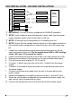
Table of Contents Listing and Code Approvals. . . . . . . . . . . . . . . . . . . . . . . . . . . . . . . . . . . 3 Model Specifications. . . . . . . . . . . . . . . . . . . . . . . . . . . . . . . . . . . . . . . . .3 Step-by-Step Installation . . . . . . . . . . . . . . . . . . . . . . . . . . . . . . . . . . . . .3 Section A: Installation information . . . . . . . . . . . . . . . . . . . . . . . . . . . . . 4 Framing Dimensions . . . . . . . .
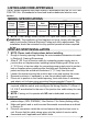
LISTING AND CODE APPROVALS The BF series fireplaces have been tested in accordance with the UL 2021 and CSA C22.2 No. 46 standards for fixed and location-dedicated electric room heaters. MODEL SPECIFICATIONS Voltage (Volts) Rated Power (Watts) Remote Control Wall Thermostat 120/120/ 208/240 8/1223/ 1823/2423 3 Stage Optional No Heat 120 Volt 0.07A AMPS 120 208 Volt Volt 10.2A 8.7A 240 Volt 10.
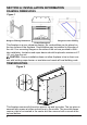
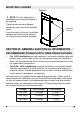
SECTION A: INSTALLATION INFORMATION FRAMING DIMENSIONS Figure 1 Rough-In Framing Dimensions Firebox Dimensions Rough-In Corner Framing This fireplace is a zero clearance design. No combustibles can be placed on the top surface of the fireplace. Combustibles may be installed to the edge of the unit. Four mounting flanges on the sides of the unit are provided to facilitate installation. Insulation and vapor barrier should be placed a minimum of 2” (5.1 cm) from the unit.
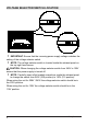
MOUNTING FLANGES Figure 3 ! NOTE: The trim should be installed before securing the firebox in the opening. There are two mounting flanges located on each side of the fireplace insert. Mounting Flanges From the inside of the unit, bend tabs outward and mount to the inside of the framing using suitable hardware.
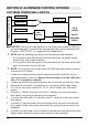
VOLTAGE SELECTOR SWITCH LOCATION ! IMPORTANT: Ensure that the incoming power supply voltage matches the setting of the voltage selector switch. ! NOTE: The voltage selector switch is located inside the exhaust panel on the top right hand corner. CAUTION: When changing the voltage selector switch from 240V to 120V ensure that the power supply is turned off. ! NOTE: Carefully insert a flat headed screwdriver inside the exhaust panel to change the switch from 240V (230 position) to 120V (115 position).
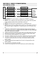
SECTION C: DIRECT POWER WIRING FIREPLACE JUNCTION BOX 240V INSTALLATION WHITE WIRE - N WHITE WIRE - N RED WIRE – L2 RED WIRE – L2 240 V POWER BLACK WIRE – L1 BLACK WIRE – L1 GREEN WIRE - G GROUND WIRE - G SUPPLY (BREAKER PANEL) ! IMPORTANT: The unit is factory configured for 208/240V operation. ! NOTE: Use 3 conductor wires with ground (4 wires total) from the power supply (breaker panel) to the junction box on the unit. ! NOTE: All wiring must be completed prior to installing the unit.
FIREPLACE JUNCTION BOX 120V INSTALLATION WHITE WIRE - N WHITE WIRE - N RED WIRE – L2 BLACK WIRE – L1 GREEN WIRE - G 120 V BLACK WIRE – L1 GROUND WIRE - G POWER SUPPLY (BREAKER PANEL) ! IMPORTANT: The unit is factory configured for 208/240V operation. ! NOTE: Use 2 conductor wires with ground (3 wires total) from the power supply (breaker panel) to the junction box on the unit. ! NOTE: All wiring must be completed prior to installing the unit.
120V INSTALLATION - NO HEAT INSTALLATION FIREPLACE JUNCTION BOX WHITE WIRE - N WHITE WIRE - N RED WIRE – L2 BLACK WIRE – L1 BLACK WIRE – L1 GREEN WIRE - G GROUND WIRE - G SUPPLY (BREAKER PANEL) RED - 1 RED - 2 120 V POWER WIRE NUTS ! IMPORTANT: The unit is factory configured for 208/240V operation. ! NOTE: Use 2 conductor wires with ground (3 wires total) from the power supply (breaker panel) to the junction box on the unit. ! NOTE: All wiring must be completed prior to installing the unit.
SECTION D: ALTERNATE CONTROL OPTIONS 120V MAIN POWER WALL SWITCH FIREPLACE JUNCTION BOX WHITE - N WHITE – N RED – L2 120 V BLACK – L1 WALL SWITCH GROUND - G POWER BLACK – L1 SUPPLY GROUND - G (BREAKER PANEL) CAUTION: The use of a wall switch to control the main power for 240V is not recommended. To control the unit remotely the use of a Dimplex Wall Remote - WRCPF-KIT - is suggested (sold seperately).
9. 10. 11. 12. 13. 14. Connect Ground (green) from the unit to the Ground (green) wire of the main power wall switch by using a wire connector (not supplied). Connect L1 (black) wire from the power supply to the L1 terminal of the main power wall switch. Secure the 2 remaining Ground wires (green) with a ground screw in the main switch wall box. Ensure that all connections are tight. Insert all the wiring of the main power wall switch into the main switch wall box.
0V MAIN POWER WALL SWITCH - NO HEAT WHITE - N FIREPLACE JUNCTION BOX WHITE – N RED – L2 BLACK – L1 120 V WALL SWITCH RED – 2 RED – 1 POWER BLACK – L1 (BREAKER PANEL) WIRE NUTS GROUND - G SUPPLY GROUND - G ! NOTE: Before installing the unit have the following wires installed: • A 2 conductor wire with ground (3 wires total) from the power supply panel to the main switch wall box. • A 2 conductor wire with ground (3 wires total) from the main switch wall box to the junction box on the unit.
power wall switch. 11. Locate and separate by wire nut the 1 (red) and 2 (red). 12. Secure the 2 remaining Ground wires (green) with a ground screw in the main switch wall box. 13. Ensure that all connections are tight. 14. Insert all the wiring of the main power wall switch into the main switch wall box. 15. Insert all the wiring back into the unit and secure with a cable clamp.
FIREPLACE JUNCTION BOX 120V HEATER WALL SWITCH CONTROL RED – 2 RED – 1 WALL SWITCH GROUND - G CAUTION: The use of a wall switch to control the heater for a 240V installation is not recommended. To control the heater remotely the use of a Dimplex Wall Remote - WRCPF-KIT - is suggested (sold seperately). ! NOTE: Before installing the unit complete the following: • Install main power connection with appropriate wiring - directly to the main power or through a wall switch.
G FROM UNIT G FROM POWER SUPPLY G FROM UNIT L1 FROM UNIT WIRE 2 FROM UNIT NEUTRAL FROM UNIT AND SUPPLY L1 FROM POWER SUPPLY WIRE 1 FROM UNIT 1 2 G 2 CONDUCTOR WIRE FROM HEATER SWITCH ! NOTE: This only illustrates 2 1 G heater switch connection, see previous sections for main power connection instructions.
unit. ! NOTE: The following installation instructions are for a single pole thermo1. 2. 3. 4. 5. 6. 7. 8. 9. 10. 11. 12. 13. stat. Loosen the screw securing the junction box and remove the cover. Remove the knockouts (if necessary) or use the provided cable clamp. Pull out the three wires marked 1, 2, and G (red, red, and green). Remove the wire connector and separate the wires marked 1 & 2.
FIREPLACE JUNCTION BOX 120V / 240V WALL MOUNTED FLAME OVERRIDE SWITCH BLUE – 4 BLUE – 3 WALL SWITCH GROUND - G DO NOT USE WITH NO HEAT INSTALLATIONS ! NOTE: The fireplace can be wired to have a wall switch operate the flame independent of the heater. ! NOTE: Before installing the unit complete the following: • Install main power connection with appropriate wiring - directly to the main power or through a wall switch.
G FROM UNIT G FROM POWER SUPPLY G FROM UNIT L1 FROM UNIT WIRE 4 FROM UNIT NEUTRAL FROM UNIT AND SUPPLY L1 FROM POWER SUPPLY WIRE 3 FROM UNIT 1 2 G 2 CONDUCTOR WIRE FROM FLAME OVERRIDE SWITCH ! NOTE: This only illustrates 4 flame switch connection, see previous sections for main power connection instructions.
Dimplex North America Limited 1367 Industrial Road Cambridge, ON Canada N3H 4W3 © 2016 Dimplex North America Limited LED STRIP LED DRIVER BOARD F T F F F T F F T T F T F HEATER ASSEMBLY T T F F T F 240V/LOW HEAT 120V/LOW HEAT LOGSET DRIVER 230 2B 4B 6B 1A 3A 5A 240V/HI HEAT 120V/HI HEAT J REMOTE CONTROL RECEIVER SWITCH BOARD 4B 5B 1A 2A MAIN ON/OFF SWITCH VOLTAGE SELECTOR 4 3 N G 1 2 L2 L1 FOR HOOK UP TO OPTIONAL FLAME OVER-RIDE SWITCH FOR HOOK UP TO OPTIONAL WALL THERMOS