
Installation Guide
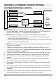


Table Of Contents

14
www.dimplex.com
CAUTION: The use of a wall switch to control the heater for a 240V instal-
lation is not recommended. To control the heater remotely the use of a
Dimplex Wall Remote - WRCPF-KIT - is suggested (sold seperately).
!
NOTE: Before installing the unit complete the following:
• Install main power connection with appropriate wiring - directly to the
main power or through a wall switch.
• Install a 2 conductor wire with ground (3 wires total) from the heater
switch wall box to the junction box on the unit.
!
NOTE: Use a heater wall switch (On/Off) that is rated for a minimum of 15
amps.
1. Loosen the screw securing the junction box cover and remove the cover.
2. Remove the knockouts (if necessary) or use the provided cable clamp.
3. Pull out the three wires marked 1, 2, and G (red, red, and green).
4. Remove the wire connector and separate the wires marked 1 and 2.
5. Connect the 1 wire (red) from the unit to the L1 wire (black) from the
heater wall switch by using a wire connector (not supplied).
6. Connect the other end of L1 wire (black) from the heater wall switch to the
L1 terminal of the heater wall switch.
7. Connect the 2 wire (red) from the unit to the Neutral wire (white) from the
heater wall switch using a wire connector (not supplied).
8. Connect the other end of the Neutral wire (white) from the heater wall
switch to the L2 terminal of the heater wall switch.
9. Connect the Ground wire (green) from the unit to the Ground wire (green)
from the heater wall switch using a wire connector (not supplied).
10. Secure the remaining Ground wire (green) with a ground screw in the
heater switch wall box.
11. Ensure that all connections are tight.
12. Insert all the wiring of the heater wall switch into the heater switch wall
box.
13. Insert all the wiring back into the unit and secure with a cable clamp.
120V HEATER WALL SWITCH CONTROL
FIREPLACE JUNCTION BOX
RED – 2
WALL
SWITCH
RED – 1
GROUND - G