
Installation Guide
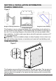
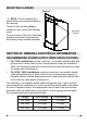
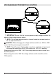
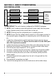
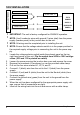
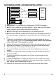
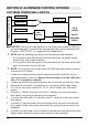
Table Of Contents

4
www.dimplex.com
FRAMING DIMENSIONS
Rough-In Framing Dimensions
Firebox Dimensions
Rough-In Corner Framing
This replace is a zero clearance design. No combustibles can be placed on
the top surface of the replace. Combustibles may be installed to the edge of
the unit. Four mounting anges on the sides of the unit are provided to facili-
tate installation. Insulation and vapor barrier should be placed a minimum of 2”
(5.1 cm) from the unit.
CAUTION: Ensure installation does not allow replace to be in direct con-
tact with building vapor barrier or insulation and meets all local building code.
TRIM MOUNTING
This replace comes with three trim pieces, top and two sides. The top piece is
secured with screws at either end and one in the middle. The two side pieces
require a tab to be inserted in the center slot then secured with a screw at the
top and bottom.
SECTION A: INSTALLATION INFORMATION
Figure 1
Figure 2