
Installation Guide
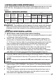
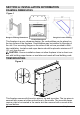
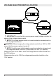
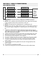
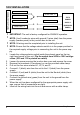
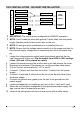
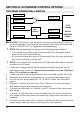
Table Of Contents

7
!
IMPORTANT: The unit is factory congured for 208/240V operation.
!
NOTE: Use 3 conductor wires with ground (4 wires total) from the power
supply (breaker panel) to the junction box on the unit.
!
NOTE: All wiring must be completed prior to installing the unit.
!
NOTE: Ensure that the voltage selector switch is in the proper position for
the required supply voltage prior to connecting the unit to the power sup-
ply.
1. Locate the voltage selector switch inside the exhaust panel on the top
right hand corner of the unit. Ensure that the switch is in the 240V posi-
tion. (230 is printed on switch)
2. Loosen the screw securing the junction box cover and remove the cover.
3. Remove the knockouts (if necessary) or use the provided cable clamp.
4. Pull out the four wires marked L1, L2, N, and G.
5. Connect L1 (black) from the unit to the L1 (black) from the power supply.
6. Connect L2 (red) from the unit to the L2 (red) from the power supply.
7. Connect N (white) from the unit to the to the Neutral (white) from the
power supply.
8. Connect the ground wire (green) from the unit to the ground from the
power supply.
9. Ensure that all connections are tight.
10. Insert all the wiring back into the unit and secure with a cable clamp.
240 V
POWER
SUPPLY
(BREAKER
PANEL)
FIREPLACE JUNCTION BOX
WHITE WIRE - N
RED WIRE – L2
BLACK WIRE – L1
GREEN WIRE - G
WHITE WIRE - N
RED WIRE – L2
BLACK WIRE – L1
GROUND WIRE - G
SECTION C: DIRECT POWER WIRING
240V INSTALLATION