Owner’s Manual Model BLF50 IMPORTANT SAFETY INFORMATION: Always read this manual first before attempting to install or use this fireplace. For your safety, always comply with all warnings and safety instructions contained in this manual to prevent personal injury or property damage. To view the full line of Dimplex products, please visit www.dimplex.
Table of Contents Welcome & Congratulations. . . . . . . . . . . . . . . . . . . . 3 IMPORTANT INSTRUCTIONS. . . . . . . . . . . . . . . . . . 4 Quick Reference Guide . . . . . . . . . . . . . . . . . . . . . . . 7 Fireplace Installation . . . . . . . . . . . . . . . . . . . . . . . . . 8 Site Selection. . . . . . . . . . . . . . . . . . . . . . . . . . . . . . . . . . . . . . . 8 Hardwire Installation. . . . . . . . . . . . . . . . . . . . . . . . . . . . . . . . . . 9 Wiring. . . . . . . . . . . . . . .
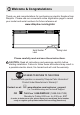
Welcome & Congratulations Thank you and congratulations for purchasing an electric fireplace from Dimplex. Please use our convenient online registration page to record your model and serial numbers for future reference at www.dimplex.com/register Serial Number Label Rating Label Please carefully read and save these instructions. CAUTION: Read all instructions and warnings carefully before starting installation.
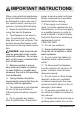
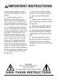
IMPORTANT INSTRUCTIONS When using electrical appliances, basic precautions should always be followed to reduce the risk of fire, electric shock, and injury to persons, including the following: ① Read all instructions before using this electric fireplace. ② This fireplace is hot when in use. To avoid burns, do not let bare skin touch hot surfaces. The surface around the heater outlet becomes hot during heater operation. DANGER: High temperatures may be generated under certain abnormal conditions.
IMPORTANT INSTRUCTIONS in areas where gasoline, paint, or flammable liquids are used or stored. ⑮ Use this heater only as described in this manual. Any other use not recommended by the manufacturer may cause fire, electric shock or injury to persons. ⑯ To reduce the risk of electric shock, this appliance has a polarized plug (one blade is wider than the other). This plug will fit in a polarized outlet only one way. If the plug does not fit fully in the outlet, reverse the plug.
IMPORTANT INSTRUCTIONS WARNING: Remote control contains small batteries. Keep away from children. If swallowed, seek medical attention immediately. WARNING: Do not install battery backwards, charge, put in fire or mix with used or other battery types - may explode or leak causing injury. ! NOTE: Changes or modifications not expressly approved by the party responsible for compliance could void user's authority to operate the equipment.
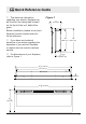
Quick Reference Guide ① The electrical information regarding your electric fireplace can be found on the rating label located on the front of the unit, behind the glass. Figure 1 Before installation, please record your fireplace's serial number below for future reference. ② If you have any technical questions or concerns regarding the operation of your electric fireplace, or require service contact customer service. ③ For dimensions of your fireplace, refer to Figure 1. 7" (17.8 cm) 16" (40.
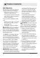
Fireplace Installation Site Selection Review and consider all of the following conditions for installation: • Dimensions of the unit: 505/16" (128cm) x 19½"(49.5cm) • Unit requires a minimum of two wall studs in order to ensure a secure installation Three possible installation methods: • Surface mount (pg. 12); In-wall Recessed (pg. 13); or Flush mount (pg.
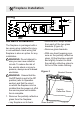
Fireplace Installation Wiring L1 120V~ 60Hz RL3 M Hardwire Installation The fireplace is packaged with a two prong plug installed for plugin convenience. Hard wiring the fireplace is also an option for any installation. WARNING: Do not attempt to wire your own new outlets or circuits. To reduce the risk of fire, electric shock or injury to persons, always use a licensed electrician.
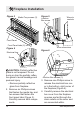
Fireplace Installation Figure 3 Media Tray screws (2) Figure 5 Wires to controls Junction Box screw Front Panel Front Panel tabs (2) Figure 4 Electrical box Wire connectors Figure 6 Screw CAUTION: Partially reflective glass is not tempered. Do not bump or drop the partially reflective glass to avoid breakage and personal injury. • Remove partially reflective glass from fireplace. 2. Remove six Phillips screws that fasten the media tray and two screws that fasten the front panel tabs (Figure 3).
Fireplace Installation 5. Unscrew the two wire connectors inside the electrical box and separate the wires (Figure 5). 6. Remove the one Phillips screw that attaches the junction box cover to the fireplace chassis (Figure 5) from inside. 7. From the back of the fireplace, remove the remaining three Phillips screws which hold the junction box to the fireplace chassis (Figure 6). 8. Pull the junction box and power cord out the front of the fireplace. 9.
Fireplace Installation cover over the wires and connectors and attach to fireplace chassis using the screw removed in step 3. 15. Carefully reinsert partially reflective glass into fireplace and anchor in place using glass brackets and screws removed in step 1. 16. Refer to Front Glass Installation section, page 16 for final installation procedures. For Bathroom Use If this unit is installed in a bathroom it must be protected by a GFI receptacle or circuit.
Fireplace Installation Figure 9 Key-hole Wall stud Permanent mounting hole the partially reflective glass to fall out of the inside framing. CAUTION: Partially reflective glass is not tempered. Do not bump or drop the partially reflective glass to avoid breakage and personal injury. • Remove partially reflective glass from fireplace. 4. Position the fireplace on a wall at the position where it will be mounted (Figure 9). Use a bubble level (one is supplied) to ensure that fireplace is level on the wall.
Fireplace Installation Figure 10 2 x 4 Framing 12.Carefully replace and install partially reflective glass and glass brackets using screws from step 1. 13.Refer to Front Glass Installation section, page 17 for final installation procedures. for 1/4 in. (6.4 mm) around the fireplace insert for ease of installation. This fireplace does not require any additional venting. 2.
Fireplace Installation Figure 12 Mounting hole electric shock or injury to persons, always use a licensed electrician. Ensure that the On/Off Switch is set to the Off position (refer to Operation section) and that the circuit on which the fireplace is to be installed has the power cut off at the service panel until installation is complete. 3. Lift fireplace and insert into opening (Figure 11). 4. Use bubble level (supplied) to level the fireplace within the framing. Adjust as required. 5.
Fireplace Installation • Plug in (you may run the power cord out of the framed wall opening to an existing outlet or install an outlet on a nearby wall stud within the wall). • Hard wire the fireplace (recommended). Follow the hard wiring instructions on page 9. WARNING: Do not attempt to wire your own new outlets or circuits. To reduce the risk of fire, electric shock or injury to persons, always use a licensed electrician.
Fireplace Installation Front Glass Installation 1. Evenly distribute supplied glass rock on the front tray of the fireplace (Figure 15). 2. Carefully mount front glass assembly so that the front glass hooks (4) hang on the front glass mounts on the fireplace (4) (Figure 16). 3. Use the supplied two Phillips sheet metal screws to fasten the glass assembly tabs to the fireplace (Figure 17). 4. Ensure the fireplace's On/Off Switch is switched to the Off position (refer to operation section). 5.
Operation Figure 18 C B A WARNING: This electric fire- box must be properly installed before it is used. The manual controls for the electric fireplace are located on the right side of the unit and inside the air intake slot (Figure 18). A. On/Off Switch The On/Off Switch supplies power to all fireplace functions. When the switch is in the “ I ” position, the unit is on. When in the “ O ” position, the fireplace is off. B.
Operation back on without being reset. It can be reset by switching the On/ Off Switch to Off and waiting five (5) minutes before switching the unit back on. CAUTION: If you need to continuously reset the heater, disconnect power and call Dimplex customer service at 1-888-DIMPLEX (1-888-346-7539). Remote Control The fireplace is supplied with a radio frequency remote control. This remote control has a range of approximately 50 feet (15.
Operation on the remote control. 5. Press any button on the remote control within that 10 seconds. This will synchronize the remote control and receiver. Remote Control Usage The remote control operates the fireplace levels sequentially (from off): flames only; to flames and low heat; to flames and high heat. The level is increased every time the ON button is pressed on the remote control and the fireplace can be turned off at any point by pressing the OFF button.
Maintenance WARNING: Disconnect power and allow heater to cool before attempting any maintenance or cleaning to reduce the risk of fire, electric shock or damage to persons. ! NOTE: The fireplace should not be operated with an accumulation of dust or dirt on or in the unit, as this can cause a build up of heat and eventual damage. For this reason the heater must be inspected regularly, depending upon conditions and at least at yearly intervals.
Warranty Products to which this limited warranty applies This limited warranty applies to your newly purchased Dimplex electric fireplace. This limited warranty applies only to purchases made in any province of Canada except for Yukon Territory, Nunavut, or Northwest Territories or in any of the 50 States of the USA (and the District of Columbia) except for Hawaii and Alaska. This limited warranty applies to the original purchaser of the product only and is not transferable.
Warranty or part without charge. If Dimplex is unable to repair or replace such product or part, or if repair or replacement is not commercially practicable or cannot be timely made, Dimplex may, in lieu of repair or replacement, choose to refund the purchase price for such product or part. • Limited warranty service will be performed solely by dealers or service agents of Dimplex authorized to provide limited warranty services.
Technical Support Technical and troubleshooting support, as well as a list of replacement parts can be found on www.dimplex.com/customer_support. Dimplex North America Limited 1367 Industrial Road Cambridge ON Canada N4H 4W3 © 2016 Dimplex North America Limited 24 www.dimplex.