A Class Heat Pump Cylinders Up to 250L EC-Eau Cylinder Range Installation and User Instructions Important - This manual must be left with the user after Installation!
Benchmark places responsibilities on both manufacturers and installers. The purpose is to ensure that customers are provided with the correct equipment for their needs, that it is installed, commissioned and serviced in accordance with the manufacturer’s instructions by competent persons and that it meets the requirements of the appropriate Building Regulations.
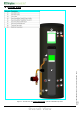
0 Overall View 08 02 03 07 06 01 05 04 Figure 1: Overall view of A Class Heat Pump Cylinder installation process Overall View A Class HP Installation and User Instructions R02583-2 09/13 Page 3 09
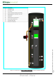
10 02 03 09 08 11 06 01 05 04 Figure 2: Overall view of Solar A Class Heat Pump Cylinder installation process Overall View A Class HP Installation and User Instructions R02583-2 09/13 Page 4 07
1 Contents 0 Overall View ............................................................................................................. 3 1 Contents ................................................................................................................... 5 2 Introduction ............................................................................................................. 7 3 Scope of delivery ..................................................................................................
9 Technical data ........................................................................................................ 23 9.1 A Class Heat Pump Buffer Range .......................................................................... 23 9.2 Heat Pump Buffer Solar Thermal Range ................................................................. 25 9.3 Cylinder heat exchanger pressure drop ................................................................. 27 9.4 Cylinder Attainable Temperature ..........
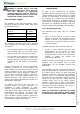
2 Introduction 3 Thank you for choosing a Dimplex product. The EC-Eau heat pump cylinders are specified with large, high surface area heat exchangers, specifically sized to match the requirements of Dimplex “A” Class Heat Pumps. They boast 60mm of low GWP insulation foam, together with 100% recyclable stainless steel inner components and a sleek black, hard wearing outer shell manufactured from completely recycled materials.
Pre-Installation advice Please read the following section carefully before commencing installation. If in any doubt, please call the appropriate help desk. Disregarding the instructions given in this manual in its entirety and any relevant regulations, standards and codes of practice will void the guarantee of this product. Handling – depending on the size of the unit and access to its installation location, consideration must be given to the handling of the unit.
4.3 Cold water supply For satisfactory and safe performance of the unvented cylinder the water supply must meet the following criteria: Minimum dynamic pressure Maximum inlet supply pressure Minimum flow rate Max. chlorine content Max. water hardness 150 kPa (1.5 bar) 1200 kPa (12 bar) 15 l/min 250mg/L 200mg/L 4.
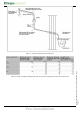
Table 2: Sizing of copper discharge pipe “D2” for common temperature relief valve outlet sizes Pre-Installation A Class HP Installation and User Instructions R02583-2 09/13 Page 10 Figure 3: Typical discharge pipe arrangement
4.4.2 Worked example cross-linked polyethylene (PE-X) complying with national standards. From Table 2, the maximum resistance allowed for a straight length of 22mm copper discharge pipe (D2) from a G½ temperature relief valve is 9.0m. Subtract the resistance for 4 No. 22mm elbows at 0.8m each = 3.2m. Therefore the maximum permitted length equates to 5.8m, which is less than the actual length of 7m, therefore calculate the next largest size. 4.4.
5 Installation 5.1 Cold Water Inlet Control Group with Inlet 5.1.1 Correctly site the cylinder Install the cylinder in an appropriate location, ensuring all of the recommendations have been considered (see chapter 4.2). 5.1.2 Install the inlet group The inlet group regulates the pressure of the incoming mains water supply to the cylinder and removes any debris that might be water borne. It is important to check the pre-charge pressure of the expansion vessel membrane before filling the cylinder.
5.1.4 Balanced cold water supply the safety device, e.g. temperature relief valve. If a balanced cold water supply is required (recommended) a connection can be taken from the bottom of the inlet group. Where a manifold is used it should be sized to accept and discharge the total discharge from all the D1 discharge pipes connected to it. The discharge pipe work from the expansion relief valve must be installed constantly falling to an open point of discharge.
Note: The cylinder must be filled with water before switching on the immersion heater. Failure to do so will damage the element and void any guarantee on the product. 5.4 HP flow to buffer connection The cylinder buffer flow connection must be connected to the three port valve, connection B. See Figure 6. 5.5 Buffer flow to HP connection The cylinder buffer flow to HP connection must be connected in series with the heat emitter system/under floor heating. 5.
Installation A Class HP Installation and User Instructions R02583-2 09/13 Page 15 Figure 7: Wiring configuration of space heating and hot water - Dimplex "A Class" cylinder
5.8.1 Primary Electrical Connections All wiring must be carried out by a suitably qualified person and must be fully compliant with the current release of Building & Wiring Regulations. For general wiring configuration see Figure 7. In both retro fit and new build installations, a 3 core cable must be taken from the isolator [typically a 16Amp double pole fused spur] and connected to the primary connector block as illustrated in Figure 8.
Modbus Connection Correct installation of the Modbus connections is critical for communication between the heat pump, UI and the cylinder. Figure 9 illustrates how these connections must be made. The modbus wire must be specified to BELDEN 9842. The maximum allowable network length is 100m. Modbus in connection comes from the heat pump master controller. Modbus out connection goes to the user interface. The earth shield of the Modbus connection must be connected to ground at both ends.
Figure 10: Zone connection & Temperature The water module contains 5 optional digital inputs, 4 optional NTC zone temperature sensor inputs and 1 domestic hot water (DHW) NTC sensor. • • DHW NTC is pre-wired and fitted to the cylinder. This sensor allows the user interface to display the actual cylinder temperature. NTC zone sensors allow the user interface to display room temperature in up to 4 different zones and actuate the corresponding controls accordingly.
Figure 11: Digital Inputs & Temperature Sensors 5.8.5 Solar High Limit Stat Wiring Live From Solar Controller Live To Solar Circulation Pump/Valve Figure 12: Solar High Limit Stat Wiring Installation A Class HP Installation and User Instructions R02583-2 09/13 Page 19 The DHW cylinder solar zone valve/circulation pump must be wired through the cylinder high limit stat as illustrated in Figure 12. (Applicable to ECS250HPST40A-580 only).
5.9 Bivalent System 10) Check all shower outlets, toilet cisterns and other draw off points for leaks or dripping (especially when replacing a vented unit). Open all water outlets to purge air from pipe work and ensure proper operation. 11) Adjust timer programmer and cylinder thermostat settings in accordance with client requirements. 12) Follow the instructions for commissioning the heat pump as per heat pump installation manual. 13) Commission the user interface as per UI installation manual.
Maintenance 8) Periodically the immersion heaters should be removed cleaned and the unit flushed out. Check the O-ring seal for damage and replace if necessary. A torque of 40 Nm is recommended when tightening up the immersion after it has been removed and refitted. 9) Check electrical wiring connections and the condition of the cable of the immersion heater, the thermostat and the connections on the relays.
Spare Parts Description Part No A Class 22mm x 3bar Inlet control group R00041-1 P Inlet control group PRV cartridge R00009-1 P 19 litre expansion vessel R00045-2 P 24 litre expansion vessel R00046-2 P Expansion vessel fixing kit R00094-1 P DN16 3/4" BSP x 1000 flex pipe R00095-1 P 1/2" BSP T&P valve R00020-1 P 15 x 22 straight PE tundish R00047-1 P 1 3/4" 3kW Imm htr C W rodstat R00019-2 P Immersion heater element R00089-1 P Imm heater rodstat R00090-1 P 3kW Titanium Imm
9 Technical data 9.1 A Class Heat Pump Buffer Range Figure 14: A Class Heat Pump Cylinder and Cross-section (for reference only) Reference Weight [kg] 150 42 210 50 250 62 Weight full [kg] 226 295 344 8 13 18 Reheat time [mins]* Average draw off temperature [°C]* 58 58 60 125 193 246 Heat loss [kWh]* 0.42 1.31 0.42 1.53 0.42 1.
Actual capacity [L] Materials - inner cylinder - outer cylinder - inlet/outlet - coils - insulation Maximum operating conditions - potable water temperature - heating water temperature - operating pressure - max. design pressure Cold water supply - minimum dynamic pressure - maximum static pressure - minimum flow rate Connections - cold water inlet - hot water outlet - coil flow and return Coil specification - heat pump coil surface area [m²] - HX performance heat pump coil [kW] - max. working pres.
9.2 Heat Pump Buffer Solar Thermal Range Figure 15: A Class Solar Heat Pump Cylinder and Cross-section (for reference only) Reference 250 HP coil Weight [kg] 250 solar coil 66.5 Weight full [kg] 349 Reheat time [mins]* 7.4 29 Average draw off temperature [°C]* 57 59 120 242 0.42 0.
Table 6: A Class Heat Pump Cylinder Product features # Not including insulation Technical Data A Class HP Installation and User Instructions R02583-2 09/13 Page 26 A Class Solar Heat Pump Cylinder Range 250 Reference 150 243 Actual capacity [L] 210 145 Aux. hot water capacity [L] 120 210 210 Dedicated solar storage vol. [L] 123 250 250 Solar coil volume [L] 2.
9.3 Cylinder heat exchanger pressure drop 1.1m2 Coil Pressure Drop 180000 160000 Pressure Drop (Pa) 140000 120000 100000 80000 60000 40000 20000 0 0.0 0.5 1.0 1.5 Flow Rate 2.0 2.5 (m3/h) 2.2m2 Coil Pressure Drop 45000 40000 30000 25000 20000 15000 10000 5000 0 0.0 0.5 1.0 1.5 2.0 Flow Rate (m3/h) Figure 16: Heat exchanger pressure drop for 1.1m² and 2.2m² coils Technical Data 2.
The heat pump heating system must be commissioned by a trained installer. Ensuring correct installation of the system will allow a water temperature of 60°C to be obtained inside the cylinder during DHW preparation. This is true for all cases when ambient conditions are between -2°C and +25°C. For other operating conditions, i.e. -2°C < ambient > 25°C, cylinder temperatures of approximately 55°C can be expected.
10.4 Maintenance The maintenance of this appliance must be carried out by a suitably qualified person only. It is recommended to maintain the unit on an annual basis. Isolate all electrical supplies from the unit before commencing work. Danger of electrical shock! See Section 7. 10.5 Troubleshooting B No hot water C Intermittent water discharge through tundish on warm-up D Continuous discharge Cause A.1 Stop valve closed A.2 Strainer blocked A.3 Pressure reducing valve fitted against flow B.
Figure 18: A Class Cylinder Wiring Overall View Wiring A Class HP Installation and User Instructions R02583-2 09/13 Page 30 11 A Class Cylinder Wiring Overall View
Wiring A Class HP Installation and User Instructions R02583-2 09/13 Page 31 Figure 19: A Class Installer Wiring Overall View
A Class HP Installation and User Instructions R02583-2 09/13 Page 34 Dimplex a division of GDC Group Ltd Millbrook House Grange Drive, Hedge End, Southampton SO30 2DF Tel.: 0845 600 5111 e-mail: aftersales@dimplex.co.uk www.dimplex.co.