
User Manual
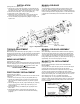
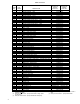
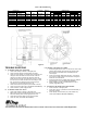

Table 2. Enclosed Housing
Figure 5.
TROUBLE SHOOTING
A. IF BRAKE DOES NOT RELEASE:
1. Check brake visually for broken or damaged parts.
2. Check for broken leadwire or bad electrical connection.
3. Check for correct voltage. Line voltage must correspond to the
voltage for which the brake coils are connected. If the line
voltage is more than 10% below the voltage for which the
brake coils are connected, the magnet will not pull in, causing
the coils to burn out within minutes. If the line voltage is more
than 10% above the voltage for which the brake coils are
connected, the coils will overheat and burn out.
4. Check for burned-out coils (coils may be charred or burned).
5. Check for excessive magnet gap. (See WEAR ADJUSTMENT.)
6. Check for failure or power supply to brake.
B. IF BRAKE DOES NOT STOP:
1. Check brake visually for broken or damaged parts.
2. Make certain hub has not shifted position on the motor shaft
and that all rotating discs are fully engaged on the hub.
3. Check that the manual release is in the normal position.
4. Check disc wear. (See WEAR ADJUSTMENT.)
C.IF BRAKE CHATTERS OR HUMS:
1. See that magnet faces are clean. To remove dirt, insert a clean
sheet of paper between magnet faces and energize brake.
Move paper around between faces to dislodge dirt, then
remove paper.
2. Check for low voltage. Magnet will not pull in, and coils will
burn out if line voltage is beyond 10% below the voltage the
brake coils are connected for.
3. See that magnet faces are parallel within tolerance. Readjust
magnet gap to “D” min. (See WEAR ADJUSTMENT.)
4. Check if shading coil (20) is cracked, broken or out of
position (single phase only).
D. IF MANUAL RELEASE DOES NOT WORK:
1. Check for broken or damaged parts.
2. Check return spring (11). Brake will not reset automatically if
this spring is broken.
3. Check quantity of shim washers (13) under release stop
screws. (See MANUAL RELEASE ASSEMBLY.)
4740 WEST ELECTRIC AVENUE ! MILWAUKEE, WI 53219 ! PHONE 414/672-7830 ! FAX 414/672-5354 ! www. dingsco.com
MODEL NO.
DIMENSIONS
D
X
ENCLOSED
SEVERE
DUTY
TORQUE
LB. FT.
WEIGHT
LBS.
THERMAL
CAPACITY
HPS/MIN
INERTIA
WK
2
LB. FT.
2
C
MAX
MIN
H
N
+
1/32
ENCL
S.D.
AC
4-81025-29
6-81025-32
25
81
15
.095
6.37
.065
.035
1.31
1.75
1.31
1.00
1.50
4-81035-29
6-81035-32
35
81
15
.095
6.37
.065
.035
1.31
1.75
1.31
1.00
1.50
4-82050-29
6-82050-32
50
87
17
.169
7.00
.065
.035
1.31
2.25
1.81
1.50
2.12
4-82070-29
6-82070-32
70
87
17
.169
7.00
.065
.035
1.31
2.25
1.81
1.50
2.12
4-83075-29
6-83075-32
75
93
19
.244
7.62
.070
.040
1.31
2.75
2.31
2.00
2.75
4-83105-29
6-83105-32
105
93
19
.244
7.62
.070
.040
1.31
2.75
2.31
2.00
2.75
4-84125-29
6-84125-32
125
99
21
.318
8.25
.080
.050
1.43
3.25
2.81
2.50
3.38
4-85175-29
6-85175-32
175
105
21
.395
8.87
.080
.050
1.31
3.87
3.44
3.12
4.00