Direct Vent Residential Gas Water Heater VAC Installation Instructions and Use & Care Guide WARNING: If the information in these instructions is not followed exactly, a fire or explosion may result causing property damage, personal injury or death. Do not store or use gasoline or other flammable vapors and liquids in the vicinity of this or any other appliance. Ultra Low NOx MODELS WHAT TO DO IF YOU SMELL GAS • Do not try to light any appliance.
WATER HEATER SAFETY Your safety and the safety of others are very important. We have provided many important safety messages in this manual and on your appliance. Always read and obey all safety messages. This is the safety alert symbol. This symbol alerts you to potential hazards that can kill or hurt you and others. All safety messages will follow the safety alert symbol and either the word “DANGER” or “WARNING.
INSTALLATION REQUIREMENTS FOR THE COMMONWEALTH OF MASSACHUSETTS For all side wall terminated, horizontally vented power vent, direct vent, and power direct vent gas fueled water heaters installed in every dwelling, building or structure used in whole or in part for residential purposes, including those owned or operated by the Commonwealth and where the side wall exhaust vent termination is less than seven (7) feet above finished grade in the area of the venting, including but not limited to decks and porch
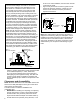
INSTALLING YOUR GAS WATER HEATER Important Information About This Water Heater Unpacking the Water Heater WARNING This gas water heater was manufactured to voluntary safety standards to reduce the likelihood of a flammable vapor ignition incident. New technology used in meeting these standards makes this product more sensitive to installation errors or improper installation environments.
WARNING FLAMMABLES Flammable Vapors Site Location • Select a location near the center of the water piping system. The water heater must be installed indoors and in a vertical position on a level surface. DO NOT install in bathrooms, bedrooms, or any occupied room normally kept closed. Note: The water heater may be installed in a closet with a door off a bedroom or bathroom providing the units are installed and vented per the manufacturer’s instructions..
IMPORTANT: The water heater should be located in an area where leakage of the tank or connections will not result in damage to the area adjacent to the water heater or to lower floors of the structure. Due to the normal corrosive action of the water, the tank will eventually leak after an extended period of time. Also any external plumbing leak, including those from improper installation, may cause early failure of the tank due to corrosion if not repaired.
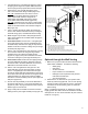
Gas Supply Figure 3 Gas Piping Manual Gas Shut-off Valve WARNING Ground Joint Union Check with local utility for minimum height 3” Minimum Explosion Hazard Use a new CSA approved gas supply line. Install a shut-off valve. Do not connect a natural gas water heater to an L.P. gas supply. Do not connect an L.P. gas water heater to a natural gas supply. Failure to follow these instructions can result in death, explosion, or carbon monoxide poisoning.
Combustion Air Supply and Ventilation WARNING Carbon Monoxide Hazard Water heater must be vented to outdoors. Vent must be installed by a qualified person using the installation instructions. Examples of a qualified person include: gas technicians, authorized gas company personnel, and authorized service persons. Failure to follow these instructions can result in death or carbon monoxide poisoning. IMPORTANT: Air for combustion and ventilation must not come from a corrosive atmosphere.
1. 2. 3. Uncompressing the corrugated Flex piping by pulling the piping to the length as required. Make sure there are two springs evenly spaced at the bend in the pipe. 4. Determine the “A” and “B” dimensions for the size of the water heater being installed (Figure 4A). Dim. “A” is measured from the center of cutout to the bottom of heater. Maximum height for all water heaters is 90”. Minimum height for 40 Gallon water heaters 68” and minimum height for 50 Gallon water heaters is 76” (Figure 4A). Dim.
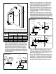
4. Extend the 3” telescoping pipe to its maximum length. Place the smaller section onto the 3” elbow at least 1 and 1/2 inches (See Figure 6). Drill two holes 180° apart and secure with the two #8 sheet metal screws provided. Apply silicone sealant to the joint. 5. Attach the larger section of the 5” telescoping pipe to the flange on the outer wall plate (See Figure 6). Drill holes 90° apart with a 1/8” drill bit and fasten with four #8 sheet metal screws (provided). Apply silicone sealant to the seam. 6.
Through The Roof Venting* Figure 7 Vertical Installation Slope down 1/4” per foot Screws Sealant HOT Screws p Ca t n Ve Inner Wall Plate Outer Wall Plate Screws & Sealant 9. Position and fasten the inner wall plate to the inside wall using an appropriate fastener for the specific wall construction. Apply silicone sealant between the inner wall plate and the inside wall. 10. Make certain the 5” telescoping pipe has been fully engaged onto the 5 inch elbow.
Vent Cap Termination WARNING Carbon Monoxide Hazard Follow all instructions to locate and install vent cap terminal. Instructions can be found in this manual, in state and local codes (or the authority having jurisdiction), or in the absence of such, the National Fuel Gas Code, ANSI Z223.1, NFPA 54, Current Edition. Do not terminate the vent cap in areas containing acid forming chemicals. Inlet air must not contain any corrosive elements.
Water System Piping Piping Installation Piping, fittings, and valves should be installed according to the installation drawing (Figure 12). If the indoor installation area is subject to freezing temperatures, the water piping must be protected by insulation. The water supply pressure should not exceed 80 psi. If this occurs, a pressure reducing valve with a bypass should be installed in the cold water inlet line.
Please note the following: • The system should be installed only with piping that is suitable for potable (drinkable) water such as copper, CPVC, or polybutylene. This water heater must not be installed using iron piping or PVC water piping. • Use only pumps, valves, or fittings that are compatible with potable water. • Use only full flow ball or gate valves. The use of valves that may cause excessive restriction to water flow is not recommended.
Temperature and Pressure Relief Valve WARNING Explosion Hazard If the temperature and pressure relief valve is dripping or leaking, have a qualified person replace it. Examples of a qualified person include: licensed plumbers, authorized gas company personnel, and authorized service personnel. Do not plug valve. Do not remove valve. Failure to follow these instructions can result in death, or explosion.
Special Applications Combination Space Heating/Potable Water System Some water heater models are equipped with inlet/ outlet tappings for use with space heating applications. Note: This water heater is suitable for combination water (potable) heating and space heating and not suitable for space heating applications only. If this water heater is to be used to supply both space heating and potable (drinking water), the instructions listed below must be followed.
Important Information About This Water Heater This gas water heater was manufactured to voluntary safety standards to reduce the likelihood of a flammable vapor ignition incident. The new technology used in meeting these standards makes this product more sensitive to installation errors. Please review the following checklist and make any required installation upgrades or changes. Installation Checklist Water Heater Location Water heater location is important and can affect system performance.
OPERATING YOUR WATER HEATER Lighting Instructions Read and understand these directions thoroughly before attempting to light or re-light the pilot. Make sure that the view port (sight glass) is not missing or damaged. See Figure 23. Make sure the tank is completely filled with water before lighting the pilot. Check the data plate near the gas control valve/thermostat for the correct gas. Do not use this water heater with any gas other than the one listed on the data plate.
FOR YOUR SAFETY READ BEFORE LIGHTING WARNING: If you do not follow these instructions exactly, a fire or explosion may result causing property damage, personal injury or loss of life. A. This appliance has a pilot which is lighted by a piezoelectric igniter. When lighting the pilot, follow these instructions exactly. B. BEFORE LIGHTING smell all around the appliance area for gas. Be sure to smell next to the floor because some gas is heavier than air and will settle on the floor.
Burner Flames Inspect the burner flames through the viewport. Flames should be very small with a blue haze and small amounts of yellow or orange at the edges. After several minutes of operation, the burner screen may glow red. If large flames are observed at any time, shut-off unit and call a qualified person. Figure 17 Flame Characteristics Correct flame soft blue Water Temperature Stacking Stacking occurs when a series of short draws of hot water (3 gallons or less) are taken from the water heater tank.
Water Temperature Regulation WARNING Water temperature over 125°F can cause severe burns instantly or death from scalds. Children, disabled and elderly are at highest risk of being scalded. Feel water before bathing or showering. Temperature limiting valves are available. The thermostat is adjusted to the pilot position when it is shipped from the factory. Water temperature can be regulated by moving the temperature dial to the preferred setting. The preferred starting point is 120°F at the “HOT” setting.
Operating the Temperature Control System Figure 19: Status Codes List of status codes are shown at top of gas control valve/thermostat. Status Light Code Normal Flashes: • 0 Flashes Indicates Control Off/Pilot Out. • 1 Flash Indicates Normal Operation. • Continuous Light indicates the gas control valve/thermostat is shutting down. Diagnostic Flashes: If the water heater is not working look for the following diagnostic flashes after lighting the pilot.
Operational Conditions Condensation Moisture from the products of combustion condenses on the tank surface and the outside jacket of the water heater and forms drops of water which may fall onto the burner or other hot surfaces. This will produce a “sizzling” or “frying” noise. NOTE: This condensation is normal and should not be confused with a leaking tank. Condensation may increase or decrease at different times of the year.
MAINTENANCE OF YOUR WATER HEATER Draining and Flushing It is recommended that the tank be drained and flushed every 6 months to remove sediment which may build up during operation. The water heater should be drained if being shut down during freezing temperatures. To drain the tank, perform the following steps: Temperature and Pressure Relief Valve WARNING 1. Turn off the gas to the water heater at the manual gas shut-off valve. 2. Open a nearby hot water faucet until the water is no longer hot. 3.
Replacement Parts Natural Gas Burner (Ultra Low Nox) Replacement parts may be ordered through your plumber or the local distributor. Parts will be shipped at prevailing prices and billed accordingly. When ordering replacement parts, always have the following information ready: Check the burner to see if it is dirty or clogged. The burner may be cleaned with soft paint brush (Figure 24). Do not use a wire brush or any tool that may damage the burner screen.
Replacing the Pilot/Thermopile Assembly 1. Remove the burner door assembly as directed previously. 2. Lift the retainer clip straight up from the back of the manifold component block (using a flat-blade screwdriver), then remove the manifold component block from the burner door assembly (Figure 25). Figure 25 Manifold Component Block Assembly Retainer Clip WARNING Thermopile Connectors Igniter Wire Pilot Tube Explosion Hazard Tighten all burner door screws securely.
Replacing the Burner Door Assembly WARNING Figure 27 Combustion Chamber Combustion Chamber Explosion Hazard Tighten all burner door screws securely. Remove any fiberglass between gasket and combustion chamber. Door Gasket Figure 28 Close-up inside view of the combustion chamber Combustion Chamber Replace viewport if glass is missing or damaged. Replace manifold component block if missing or removed. Replace door gasket if damaged.
Removing and Replacing the Gas Control Valve/Thermostat IMPORTANT: The gas control valve/thermostat is a standard valve with wire leads that connect to the thermopile. Removing the Gas Control Valve/Thermostat: 1. Turn the gas control/temperature knob to the “OFF” position (Figure 18). 2. Turn off the gas at the manual shut-off valve on the gas supply pipe (Figure 3). 3. Drain the water heater. Refer to the section of “Draining and Flushing” and follow the procedure. 4.
PROBLEM HIGH OPERATION COSTS POSSIBLE CAUSE(S) 1. 2. 3. 4. 5. 6. 7. 8. 9. CORRECTIVE ACTION Thermostat set too high Sediment or lime in tank Water heater too small for job Wrong piping connections Leaking faucets Gas leaks Wasted hot water Long runs of exposed piping Hot water piping in exposed wall 1. 2. 3. 4. 5. 6. 7. 8. 9.
STATUS LIGHT CODE TROUBLESHOOTING CHART LED STATUS 0 FLASHES (LED NOT LIT) PROBLEM CORRECTIVE ACTION Pilot light is not lit. Not enough power (millivolts) to keep it lit. Follow the lighting instructions on the front of the water heater and record any diagnostic codes. See Diagnostic Status Light Code section. 1 FLASH (EVERY 3 SECONDS) Normal operation. No corrective action necessary. 2 FLASHES Insufficient power (millivolts) to the 1. gas control valve/thermostat. 2. Check all wiring connections.
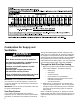
REPAIR PARTS ILLUSTRATION When ordering repair parts always give the following information: 1. 2. 3. 4. Model, serial, and product number Type of gas Item number Parts description Repair Parts List 1 2 Item No.
Listed Parts Kits and Illustrations Item 14: Manifold door gasket Item 18: Viewport Item 20: Burner Door assembly, which contains the burner, gasket, door, pilot tube, manifold component block with retainer clip, temperature sensor, and pilot assembly.
NOTES 33
NOTES 34
NOTES 35
Copyright © 2013. All Rights Reserved. Printed in the U.S.A.