
Use and Care Guide

10
“B”
“A”
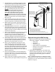
Figure 4B
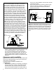
Optional Installation
NOTE:
1. Dim. “A” measured from center of cutout to bottom of heater.
2. Dim. “B” measured from center of heater to outside of wall.
3” Elbow
Screws
&
Sealant
1
2
5” Pipe
3” Elbow
Inside Cover
Plate
Screws
& Sealant
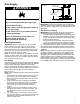
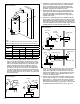
Figure 5
Vertical Installation
4. Extend the 3” telescoping pipe to its maximum length.
Place the smaller section onto the 3” elbow at least 1
and 1/2 inches (See Figure 6). Drill two holes 180°
apart and secure with the two #8 sheet metal screws
provided. Apply silicone sealant to the joint.
5. Attach the larger section of the 5” telescoping pipe to
the flange on the outer wall plate (See Figure 6). Drill
holes 90° apart with a 1/8” drill bit and fasten with
four #8 sheet metal screws (provided). Apply silicone
sealant to the seam.
6. Extend the 5” telescoping tube to its maximum length.
From outside of the building, insert a 5” tube/outer wall
plate assembly through the opening in the exterior wall
and onto the 5” elbow (See Figure 6). Seat the base of
the outer wall plate onto the exterior wall. Apply silicone
sealant between the plate and the exterior wall.
3” Pipe
Inner Wall
Plate
Screws
& Sealant
3” Telescoping
Pipe
Wall
5” Elbow
Inner Wall
Plate
Screws
& Sealant
3” Telescoping
Pipe
5” Telescoping Pipe
Outer Wall Plate
Figure 6:
Vertical Installation
7. Place the 3” tube located in the vent cap into the end
of the 3” telescoping tube (See Figure 7). Drill two
holes 180° apart with a 1/8” drill bit and secure with
two #8 sheet metal screws. Apply sealant to the joint.
Seat the cap against outer wall plate with the word
“HOT” in an upright position.
8. Secure the vent cap/outer wall plate assembly to the
exterior wall with the four 1 and 1/2” screws provided
(See Figure 7). Varying wall structures may require a
different type of screw anchor. To prevent rain from
entering the water heater vent pipe, the 5” tube should
be sloped downward towards the wall 1/4” per foot.
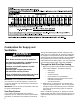
KIT
CAPACITY
40 GALLON 50 GALLON
ABAB
STANDARD 62.75” 18.00” - 24.50” 71.00” 18.00” - 24.50”
HORIZONTAL 62.75” 27.00” - 38.00” 71.00” 27.00” - 38.00”
VERTICAL 62.75” - 89-75” 18.00” - 24.50” 71.00” - 98.00” 18.00” - 24.50”
BOTH 62.75” - 89-75” 27.00” - 38.00” 71.00” - 98.00” 27.00” - 38.00”
3. If you are not using the vertical extension kit, place the
3” elbow on the flue pipe reducer on the air box and
point it in the desired direction (See Figure 8). Press
it firmly downward until seated. Drill 4 holes 90° apart
with a 1/8” drill bit and fasten the four #8 sheet metal
screws provided. Apply silicone sealant to the joint.
Install the 5” elbow over the 3” elbow and seat it into
the collar on the air box. Drill 4 holes 90° apart with a
1/8” drill bit and fasten the four #8 sheet metal screws
provided. Apply silicone sealant to the joint. Place the
inner wall cover plate over the 5” elbow. This plate will
be positioned later.
Table 2