
Use and Care Guide

9
Optional through the Wall Venting
1. Make sure a proper location has been selected for the
water heater installation. Consider the following:
• Water piping
• Gas Piping
• Access for service
• Proper clearance for combustibles
• Drainage for the temperature and pressure
relief valve and drain pan.
• Vent cap termination
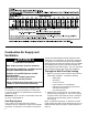
2. Determine the “A” dimension for your specific water
heater by referencing figure 4B. Cut a 6 inch opening
through the wall in the location as shown. Determine
the location of electrical wiring, pipes, or wall studs
before cutting.
NOTE: Installations requiring an “A” dimension (vertical
height) greater than what is shown as standard in the table
will require the use of a vertical extension kit (See “Vertical
Install Kit” on Page 11).
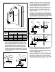
“B”
“A”
NOTE:
1. Dim.
“A” measured from center of cutout to bottom of heater.
Maximum height for all water heaters 90”,
Minimum for 40 Gallon water heaters 68”,
Minimum for 50 Gallon water heaters 76”.
2. Dim.
“B” measured from center of heater to outside of wall.
Minimum horizontal of 22“ for all water heaters at Maximum height of 90”.
Figure 4A
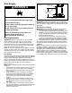
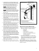
Installation Flex Vent Pipe
Outer Wall Plate
Small
Clamp
Large Clamp
Inner Wall
Plate
Upper Air Box
Reducer
Vent Cap
Assembly
Large Clamp
Small Clamp
Secure Flex Vent Pipe to Vent
Cap with Small Clamp. Apply
silicone sealant to all connections
making sure all joints are tight
and leak proof
.
Secure Flex Vent Pipe to
Reducer with Small Clamp.
Apply silicone sealant to all
connections making sure all
joints are tight and leak proof
.
1.
2.
3. Uncompressing the corrugated Flex piping by pulling
the piping to the length as required. Make sure there
are two springs evenly spaced at the bend in the pipe.
4. Determine the “A” and “B” dimensions for the
size of the water heater being installed (Figure 4A).
Dim. “A” is measured from the center of cutout
to the bottom of heater. Maximum height for all
water heaters is 90”. Minimum height for 40
Gallon water heaters 68” and minimum height
for 50 Gallon water heaters is 76” (Figure 4A).
Dim. “B” is measured from the center of water heater
to the outside of the exterior wall. Minimum horizontal
is 22” for all water heaters at the maximum height of
90” (Figure 4A).
5. Cut a 6” opening through the wall in the location as
shown. Note: location is determine first by locating all
electrical wiring, pipes, and wall studs before cutting.
6. Metal hangers may be used to keep the pipe level or
with a slope upward from the water heater through the
wall to Vent Cap.
7. At the water heater: Pull the inner 3” corrugated pipe
to the water heater’s flue reducer and attached using
the Small Clamp included in kit. Apply hi-temp silicone
sealant around the connection making sure joint is tight
and leak proof (Figure 4A).
8. Pull the outer corrugated Flex V
ent pipe down covering
the connection and secure using the Large Clamp
included in kit to the collar at the Upper Air Box
(Figure 4A). Apply hi-temp silicone sealant around the
connection making sure joint is tight and leak proof.
9. At the exterior wall: Pull the Flex Vent piping through
the Inner Wall Plate through the clearance hole from
the exterior wall to the Outer Wall Plate. Secure Inner
Wall Plate to the inside wall with 1/2” screws.
10. Pull the outer corrugated Flex Vent pipe out to the
Outer Wall Plate, secure with Large Clamp. Pull the
inner 3” corrugated pipe out from the Flex Vent pipe
through the Outer Wall Plate and attached to the end of
the 3” tube at the Vent Cap and secure using the Small
Clamp included in kit. Apply hi-temp silicone sealant
around the connection making sure the joint is tight and
leak proof (Figure 4A).
11. Secure Vent Cap Assembly to the Outer Wall Plate to
the exterior wall with four 1-1/2” screws provided in kit
(Figure 4A). Note: varying wall structures may require a
different type of screw anchor.
12. Apply hi-temp silicone sealant around the connection
making sure the joint is tight and leak proof (Figure 4A).