
Instructions / Assembly


8
Step 1: Fill the gear box with lubricant.
e gear box is shipped without lubricant. Fill the top hole with
EP90 lubricant or equivalent. e gear box holds 25 fluid oz. (0.7
liters). Fill to the bottom of the plug on the side. Do not overll as
this can cause damage to the seals. Check the oil level every 50
hours of operation.
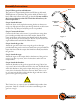
Step 2: Attach the boom.
Attach the boom to the top link mounting bracket on the tractor
using a top link pin and a lynch pin through the hole on the bottom
of the boom. Top link pin and lynch pin are not provided.
Step 3: Connect the A frame.
Connect the A frame to the tractor’s 3-point lift arms using draw
pin assembly provided, with nut and lock washer. Attach the A
frame to the boom after selecting the desired hole for adjustment
using the A frame pin and a lynch pin. e size of your tractor and
auger will determine which hole will work best.
Step 4: Attach the gear box.
Attach the gear box to the boom using the gear box draw pin
provided with the gear box and secure with cotter pins provided. e
input shaft shied and the output shaft shield are already attached to
the gear box.
Step 5: Attach the auger.
Attach the auger to the output shaft on the bottom of the gear box
using 1/2 in. hex cap screws, 1/2 in. lock washers and 1/2 in. hex
nuts provided.
Step 6: Attach the driveline.
Attach the driveline to the gear box input shaft using 5/16 in. hex
cap screw, 5/16 in. lock washer and 5/16 in. hex nut. For Model 110,
attach the driveline to the gear box input shaft using 3/8 in. hex cap
screw, 3/8 in. lock washer and 3/8 in. hex nut. Insert 1/4 in. x 3/8
in. set screw into the hole on the yoke that aligns with the 3/16 in.
groove on the gear box input shaft.
e 5/16 in. hex cap screw (3/8 in. for Model 110) provides shear
protection. Only use a Grade 5 3 in. bolt to avoid damage to the
gear box or auger.
!
ATTENTION
Assembly Instructions
Figure A
Figure B
Adjustment
Holes
“A” Frame
Boom