Model 5600 Displacement Follower Non-Contact Electro-Optical Biaxial Tracking System Diversified Optronix Corp. 116 Quirk Road Milford, CT 06460 www.divop.
Table of Contents Introduction, 1 Equipment Supplied, 1 Warnings, 1 System Assembly, 2 Theory of Operation, 3 The Lenses, 6 Lens Systems, 6 Lens Calculations, 6 Precision of the Lens Calculations, 8 Targeting, 10 Target Requirements, 10 Target Illumination, 10 Techniques of Targeting, 11 Tracking Prerequisites, 12 Focusing and System Noise, 14 High-Voltage Adjustments, 14 Equipment and Functions, 15 Front Panel Functions, 15 Operating Procedures, 17 General Operating Procedure, 17 Calibration, 20 System
Introduction The 5100 Displacement Follower is a non-contact, real-time motion measurement instrument that solves measurement problems where other instruments fail. It can measure the displacement of remote or inaccessible objects. The camera tracks the motion of the target and provides an analog output proportional to displacement. Custom optics allow a range in the field of view from 0.05” up to several feet.
System Assembly 1 Inspect the equipment for damage that might have occurred during shipment. If you find any damage, notify the shipping company immediately. 2 Attach the interconnecting cable from the control unit to the optical head and secure with the lock ring. 3 Attach the lens systems to the optical head. The lens screws into the extension barrel, and the extension barrel screws into the head. The thread system in the head is a standard Leica, 39mm diameter.
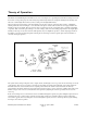
Theory of Operation The Model 5600 Biaxial Displacement Follower is a non-contacting electro-optical displacement follower designed to track the motion of a target along any axis. The moving target under study must show a sharp discontinuity in the intensity of its reflected or emitted light. The tracker is, in fact, locking onto that light/dark interface. The lens system focuses the image of the discontinuity onto the photo cathode of an image dissector tube.
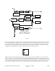
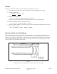
Demultiplex Data Amp Filter Deflection Servo Amp Sample/Hold Multiplex Vertical Photo-Tube Preamp Optical Head Velocity Converter Sample/Hold Multiplex Vel. / Accel Converter Horizontal Deflection Servo Amp Demultiplex Filter Data Amp model 5600 Block Diagram Figure 2 There are two possible target configurations for measuring target displacement along the vertical axis: light over dark and dark over light.
amplifiers with de-multiplex switching are connected to the vertical and horizontal coil currents, allowing the position of each edge to be obtained. De-multiplexing of the data amplifiers removes the shift current from the data output. Automatic Recapture With a light center target, dark initiates search, and with a dark center target, light initiates search. That is, if a light center target leaves the field of view, the tracker sees all dark, and begins searching.
The Lenses Lens Systems To accommodate the working distances and measurement ranges that individual applications may require, the standard lens set supplied is appropriate for a variety of situations. Included in the set are a 105mm enlarging lens, a 50mm variable-focus camera lens, and five different extension tubes.
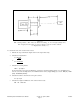
Figure56 WD = Working Distance, MR = Full scale Measurement Range, fl = Focal Length of Simple Lens, EX = Length of Extension Tube needed, D = Distance from lens to Photo Cathode, A = Magnification (usually < 1) To calculate the size of the extension tube needed: 1 Estimate the expected full-scale displacement for the target under study 2 Calculate the magnification A = 0.15 in MR in or A = 3.
Example The lens to be used in this example is the 105mm enlarging lens supplied with the system. 1 Assume that the object under study is expected to exhibit a peak-to-peak displacement of one inch. 2 Calculate the magnification: A = 0.15 in. = MR in 3 0.15 in = 0.15 1 in Calculate the working distance, WD = (1 + 1/A) fl = (1 + 1/0.15) X 105 mm = 805 mm If you prefer to have the working distance in inches, multiply by 0.03937 to obtain 31.69 inches.
Figure 6 shows that the equivalent 105mm lens cannot be considered to be located exactly at the end of the extension tube. Its equivalent position is, in fact, approximately 13mm further along the optical axis than the position used in the calculations. This positioning of the lens in its diaphragm varies with different manufacturers and no one rule will solve the problem.
Targeting Target Requirements The 5000 Series operates by locking onto a sharp discontinuity in the intensity of an object’s reflected or emitted light. The target is actually the edge that can be seen at the light-dark interface and can be made up of any combination of reflected, absorbed, or emitted light. The contrast in light intensities should be at least three to one. The greater the contrast, the easier it is to obtain lock-on and the less system output noise is produced.
high voltage to the image dissector tube may be increased. This adjustment is made on the back panel of the control unit using a small screwdriver. For high light conditions, the high voltage may be reduced, or neutral density filters can be placed in front of the lenses. Note The light source must be DC or the tracker will detect the 60 Hz change in light intensity. Techniques of Targeting There are many ways of illuminating and setting up targets.
Figure 12 Tracking Prerequisites Single Axis Tracking, Vertical or Horizontal The target and its motion should be located in the plane that is perpendicular to the optical axis. For successful lock-on, the target’s width must be greater than 10% of the full-scale measurement range, and its location must be along the tracking axis. Figure 13 The minimum target required for vertical tracking along the vertical tracking axis.
Figure 14 Biaxial Targets The 5600 can track two edges simultaneously. These edges should be perpendicular to one another, and they must share a common vertex or curved surface. See Figures 15 and 16. Figure 15 With the controls set for biaxial mode and using a light center target, and the target phase switches it to light over dark with light to the right, the systems will lock-on to the edges as shown in Figure 15.
L/D, D/L, D-L, or L-D, the system can be made to follow any of the four corners of a small square (or circle) placed in the measurement range. Figure 16 shows a dark center target in the range of measurement,. To follow these two edges, the biaxial target switch must be set to dark center and the phase switches must be set to dark over light with light to the left.
Equipment and Functions Front Panel Functions Figure 17 6 5 2 Horizontal Biaxial Power Off 7 Vertical Light Level 3 1 4 Vert. Gain 10 Displacement Output Filter 8 9 Horz. gain 11 12 100HZ OFF 10KHZ Vert Vel 13 10 3 10 1 .3 .1 30 100 14 Horz Vel 300 .03 Time ms Vert Vel Vert Acc 3 1 .3 .1 30 100 300 15 .03 Time ms 16 17 Model 5600 Front Panel 1. 2. 3. 4. 5. 6. 7. 8. 9. 10. 11. Mode Switch Selects 4 modes plus power off.
12. 13. 14. 15. Output Filter Switch Selects one of three RC low pass filters at the displacement outputs. Vel/Accel Switch Selected (Vert.Vel & Horiz.Vel) or (Vert.Vel & Vert. Accel) at the lower outputs. Vel Time Constant Selector Selects the time constant used in calculating full scale velocity. Vel/Accel Time Constant Selector Selects time constant for whether Horiz. Vel. Or Vert. Accel. As determined by the Vel/Accel. switch. 16.
Operating Procedures General Operating Procedure 1 Prepare the target and lighting as specified. Note that the light source should be DC to eliminate the 120 Hz intensity modulation, and that the light intensity should be uniform over the target area to be measured. 2 Connect the optical head to the control unit with the cable supplied. 3 Connect the control unit to a 100-120 VAC, 50/60 Hz power source. 4 Estimate the maximum displacement you expect from the target during operations.
Figure 18 Figure 18 15 Set the Mode Switch to: Vertical – if a single light over dark or dark over light target is to be tracked vertically. Horizontal – if a light to the right or light to the left target is to be tracked horizontally. Biaxial – if both the vertical and horizontal target are to be tracked simultaneously. 16 Move the target and observe that the meter defects, showing the target position. With a light over dark target, an upward movement produces a negative voltage.
Worksheet for Parameter Measurement 1. System Field of View = FOV = inches 2. Accel. Due to gravity = 386.4 in. / sec 2 or = 9814 mm / sec millimeters 2 3. Set Velocity Time for Velocity output less than 10V P-P 4. Set Accel. time for Accel. output less than 10V P-P 5. Vel Full Scale = FOV = Vel Time (seconds) in / sec = 6. Target Vel 7. Vel Output = Sensitivity = Vel Output (peak) 5 Peak Vel Output Target Vel 8.
Calibration Resistors and capacitors have been selected to make the full-scale values on the time constant selector fall within ±5% of the value indicated. To calibrate the outputs further, it is necessary to move the target or sweep the tracker orthogonal to the plane of view and at a known velocity, making the output voltage proportional to the velocity or acceleration. The chart below shows some key frequencies for checking the velocity and acceleration outputs.
Common Problems The most common errors are: 1 Improper target phase (L/D, D/L, etc.). 2 Improper centering of tracker on target. 3 Improper illumination of target: The light source must be DC. The light intensity must be calibrated for (-20 Dark) and (+20 Light). See Operating Procedures, page 17 . 4 Improper focusing of tracker on target. See Operating Procedures, page 17 . Biaxial Displacement Follower User’s Manual Version 1.
Standard Lens Set Components of the Standard Lens Set Quantity 1 1 1 1 1 1 1 Item 105mm Enlarging Lens 50mm Camera Lens 72mm Extension Tube 10mm Extension Tube 15mm Extension Tube 20mm Extension Tube 30mm Extension Tube These charts shows some of the optical parameters that can be obtained using combinations of the above components.
Lens Calibration Data Sheet LENS CALIBRATION DATA SHEET CUSTOMER: DATE: PO#: S/N: 1 2 3 4 5 4 5 LENS NUMBER: FOCAL LENGTH: EXTENSIONS: WORKING DISTANCE: RANGE OF MEASUREMENT: GAIN SETTINGS FOR PROPER CALIBRATION 1 2 3 H H V V DIVERSIFIED ENGINEERING 283 INDIAN RIVER ROAD • ORANGE, CT • (203) 799-7875 Displacement Follower User’s Manual Version 1.
Appendix Limited Warranty Diversified Optronix Corp. (DivOp) warrants that the Model 5600 will be free from defects in material and workmanship for a period of one (1) year from the date of purchase. DivOp will, at its discretion, repair or replace any part(s) found to be defective in the Model 5600 resulting from defective workmanship, material or both. All costs for packaging and transportation to Milford, CT, are the responsibility of the customer.