SPEEDZTR Operator’s Manual SPEEDZTR 44 / 968999538 SPEEDZTR 36 / 968999539 SPEEDZTR 44 / 968999547 SPEEDZTR 36 / 968999609 SPEEDZTR 44 / 968999611 SPEEDZTR 42 / 968999689 SPEEDZTR 42 / 968999713 Please read the operator’s manual carefully and make sure you understand the instructions before using the machine.
TABLE OF CONTENTS General ............................................................. 4 Driving and Transport on Public Roads ......... 4 Towing ........................................................... 4 Operating ....................................................... 4 Safety Instructions ............................................. 8 General Operation ......................................... 8 Personal Safety Equipment ......................... 10 Slope Operation ..................................
INTRODUCTION Congratulations Thank you for purchasing a Dixon ride-on mower. This machine is built for superior efficiency to rapidly mow primarily large areas. A control panel easily accessible to the operator and a hydrostatic transmission regulated by steering controls both contribute to the machine’s performance. This manual is a valuable document. Read the contents carefully before using or servicing the machine. The following of instructions (use, service, maintenance, etc.
INTRODUCTION Good Service Husqvarna’s products are sold all over the world and only in specialized retail stores with complete service. This ensures that you as a customer receive only the best support and service. Before the product is delivered, the machine has, for example, been inspected and adjusted by your retailer. See the certificate in the Service Journal in this operator’s manual. When you need spare parts or support in service questions, warranty issues, etc.
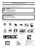
SYMBOLS AND DECALS These symbols are found on the machine and in the operator’s manual. Study them carefully so that you know what they mean. WARNING! Xxxx xxxxxx xxxxx xxxx xxxxxxxxx xxxxxx xxxxxxxxx. xx xxxxxxxx xxxx xxxxxx. Used in this publication to notify the reader of a risk of personal injury or death, particularly if the reader should neglect to follow instructions given in the manual. IMPORTANT INFORMATION Xxxx xxxxxx xxxxx xxxx xxxxxxxxx xxxxxx xxxxxxxxx. xx xxxxxxxx xxxx xxxxxx.
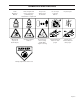
SYMBOLS AND DECALS Read Operator’s Manual Shut off engine and remove key before performing any maintenance or repair work Keep a safe distance from the machine Use on slopes no greater than 10° No passengers Whole body exposure to thrown objects Severing of fingers and toes Do not open or remove safety shields while engine is running Careful backing up, watch for other people Careful going forward, watch for other people Moving sharp blades under cover English-7
SAFETY Safety Instructions These instructions are for your safety. Read them carefully. WARNING! This symbol means that important safety instructions need to be emphasized. It concerns your safety. IMPORTANT: THIS CUTTING MACHINE IS CAPABLE OF AMPUTATING HANDS AND FEET AND THROWING OBJECTS. FAILURE TO OBSERVE THE FOLLOWING SAFETY INSTRUCTIONS COULD RESULT IN SERIOUS INJURY OR DEATH. General Operation • Read, understand, and follow all instructions on the machine and in the manual before starting.
SAFETY • Never leave a running machine unattended. Always turn off blades, set parking brake, stop engine, and remove keys before dismounting. • Disengage blades when not mowing. Shut off engine and wait for all parts to come to a complete stop before cleaning the machine, removing the grass catcher, or unclogging the discharge guard. • Operate machine only in daylight or good artificial light. • Do not operate the machine while under the influence of alcohol or drugs.
SAFETY Personal Safety Equipment WARNING! When using the machine, approved personal protective equipment (shown in illustrations) shall be used. Personal protective equipment cannot eliminate the risk of injury but it will reduce the degree of injury if an accident does happen. Ask your retailer for help in choosing the right equipment. • Make sure that you have first aid equipment close at hand when using the machine. • Never use the machine when barefoot.
SAFETY grass catchers or other attachments; they can affect the stability of the machine. Do not use on steep slopes. • Do not try to stabilize the machine by putting your foot on the ground. • Do not mow near drop-offs, ditches, or embankments. The machine could suddenly roll over if a wheel is over the edge or if the edge caves in. Children Tragic accidents can occur if the operator is not alert to the presence of children. Children are often attracted to the machine and the mowing activity.
SAFETY Maintenance WARNING! The engine must not be started when the driver’s floor plate or any protective plate for the mower deck’s drive belt is removed. Safe Handling of Gasoline To avoid personal injury or property damage, use extreme care in handling gasoline. Gasoline is extremely flammable and the vapors are explosive. • Extinguish all cigarettes, cigars, pipes, and other sources of ignition. • Use only approved gasoline container. • Never remove gas cap or add fuel with the engine running.
SAFETY General Maintenance • Never operate machine in a closed area. • Keep all nuts and bolts tight to be sure the equipment is in safe working condition. • Never tamper with safety devices. Check their proper operation regularly. • Keep machine free of grass, leaves, or other debris buildup. Clean oil or fuel spillage and remove any fuel-soaked debris. Allow machine to cool before storing. • If you strike a foreign object, stop and inspect the machine. Repair, if necessary, before restarting.
SAFETY • Ensure that nuts and bolts, especially the fastening bolts for the blade attachments, are properly tightened, torqued and that the equipment is in good condition. • Do not modify safety equipment. Check regularly to be sure it works properly. The machine must not be driven with defective or unmounted protective plates, protective cowlings, safety switches, or other protective devices. • Do not change the settings of governors and avoid running the engine with overly high engine speeds.
SAFETY • The blades are sharp and can cause cuts and gashes. Wrap the blades or use protective gloves when handling them. • Check the parking brake’s functionality regularly. Adjust and service as necessary. • The mulch blades should only be used in familiar areas when higher quality mowing is desired. • Reduce the risk of fire by removing grass, leaves, and other debris that may have accumulated on the machine. Allow the machine to cool before putting it in storage.
SAFETY Customer responsibilities • Read and observe the safety rules. • Follow a regular schedule in maintaining, caring for and using your mower. • Follow the instructions under “Maintenance” and “Storage” sections of this owner’s manual. A spark arrester for the muffler is available through your authorized Dixon dealer.
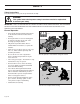
CONTROLS Controls This operator’s manual describes the Dixon Zero Turn Rider. The rider is fitted with either a Briggs & Stratton or Kohler four-stroke overhead valve engine developing 16 - 22 horse power. Transmission from the engine is made via two beltdriven hydraulic pumps, which in turn drive a hydraulic motor for each drive wheel. Using the left and right steering controls, the flow is regulated and thereby the direction and speed. 1 10 4 3 2 9 1. 2. 3. 4. 5. 6.
CONTROLS 1. Motion Control Levers The machine’s speed and direction are continuously variable using the two steering controls. The steering controls can be moved forward or backward about a neutral position. Furthermore, there is a neutral position, which is locked if the steering controls are moved outward. When both controls are in the neutral position (N), the machine stands still.
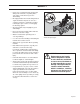
CONTROLS 2. Seat adjustment lever The seat can be adjusted lengthways. When making adjustments, sit on the seat. Slide the lever to the side and maneuver seat to appropriate placement and release lever. 3. Unlocking Transmission When pushing or pulling the mower, be sure to engage the IZT (Integrated Zeroturn Transaxle) bypass linkages. 8050-165 Seat adjustment • Always turn off engine before engaging or disengaging the hydro release (free wheel) lever.
CONTROLS 4. Refueling The machine has one fuel tank, just behind the seat. The tank capacity is 4.5 gallons (17 liters). The engine will run on a minimum of 85-octane unleaded gasoline (no oil mix). Environmentally adapted alkylate gasoline can be used. See also Technical Data concerning ethanol fuel. Methanol fuel is not allowed. When operating below 32°F (0°C) use fresh, clean winter grade gasoline to help insure good cold weather starting. 8050-768 WARNING! Fuel tank Gasoline is highly flammable.
CONTROLS 5. Ignition Switch The ignition key is placed on the driver’s panel and is used to start and stop the engine. IMPORTANT INFORMATION Do not run the starter for more than five seconds each time. If the engine does not start, wait about 10 seconds before retrying. Ignition switch 6. Choke Control The choke is used for cold starts to provide the engine with a richer fuel mixture. Two choke options are available, depending on model.
CONTROLS 8. Blade switch In order to engage the mower deck, pull the knob out; the mower blades are disengaged when the knob is depressed. Blade switch 9. Circuit breaker The circuit breaker provides protection for the electrical system by (1) 15 amp circuit breaker. If the circuit breaker trips, push the button to reset. If the condition repeats, consult a dealer for inspection and repair. Circuit breaker 10. Parking Brake The parking brake is found on the operator’s left.
CONTROLS 11. Mower Deck Cut Height Lift Lever Located to the right and front of the operator, the lift lever controls the cutting height. The deck cutting height is obtained by pressing the foot pedal forward to lift the deck. To lower the deck, apply pressure to the top side of the foot pedal and allow it to pivot while depressing the trigger and moving the lever forward. Set the desired cut height with pin. The cutting height range is from 1½" (38 mm) to 5½" (140 mm) in ½" (13 mm) increments.
OPERATION Operation Read “Safety Instructions” section and following pages, if you are unfamiliar with the machine. Training Zero turn mowers are far more maneuverable than typical riding mowers due to their unique steering capabilities. We suggest that this section be reviewed in its entirety prior to attempting to move the mower under its own power.
OPERATION Before Starting • Read the sections Safety Instructions and Controls before starting the machine. • Perform the daily maintenance before starting (see Maintenance Schedule in the Maintenance section). • Check that there is sufficient fuel in the fuel tank. • Adjust the seat to the desired position. The following conditions must be fulfilled before the engine can be started: • The driver must be seated on the seat. • • • The blade switch for engaging the mower blades must be depressed.
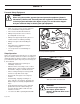
OPERATION • Move the steering controls outward to the locked (outer) neutral position. 8050-777 Steering controls in the outward, locked neutral position • Move the throttle to the middle position. • If the engine is cold, the throttle control should be pushed forward to its choke position. Set the throttle • Press in and turn the ignition key to the start position.
OPERATION • When the engine starts, immediately release the ignition key back to the run position. IMPORTANT INFORMATION Do not run the starter for more than 5 seconds each time. If the engine does not start, wait about 10 seconds before retrying. STOP 8050-781 Return to run position • Set the desired engine speed with the throttle. • Allow the engine to run at a moderate speed, “half throttle”, for 3-5 minutes before loading it too heavily. • USE FULL THROTTLE WHEN MOWING (no choke).
OPERATION To start an engine with a weak battery WARNING! Lead-acid batteries generate explosive gases. Keep sparks, flame and smoking materials away from batteries. Always wear eye protection when around batteries. If your battery is too weak to start the engine, it should be recharged. (See “Battery” in the Maintenance Section.) IMPORTANT INFORMATION Your mower is equipped with a 12-volt negative grounded system. The other vehicle must also be a 12-volt negative grounded system.
OPERATION Running 1. Release the parking brake by moving the lever downward. Your mower is equipped with an operator presence system. When the engine is running, any attempt by the operator to leave the seat without first setting the parking brake will shut off the engine. 2. Move the steering controls to the neutral position (N). 8050-783 Released parking brake 3. Select the cutting height using the cutting height pedal.
OPERATION In order, for example, to turn right while moving forward, move the right control towards the neutral position. The rotation of the right wheel is reduced and the machine turns to the right. Turning on the spot can be achieved by moving one control backward (behind the neutral position) and carefully moving the other steering control forward from its neutral position. Operating on hills Read the Safety Instructions “Driving on Slopes” in the “Safety Instructions”.
OPERATION Mowing Tips • • • • • • • • Observe and flag rocks and other fixed objects to avoid collisions. Begin with a high cutting height and reduce it until the desired mowing result is attained. The average lawn should be cut to 2½" (64 mm) during the cool season and over 3" (76 mm) during the hot months. For healthier and better looking lawns, mow often after moderate growth. For best cutting performance, grass over 6" (15 cm) in height should be mowed twice.
OPERATION Stopping the Engine Allow the engine to idle a minute in order to attain normal operating temperature before stopping it, if it has been worked hard. Avoid idling the engine for longer periods, as there is a risk of the spark plugs fouling. • Disengage the mower deck by depressing the blade switch. 8011-668 Disengage the mower deck • Raise the mower deck by depressing the pedal forward to the transport position.
OPERATION Moving by Hand WARNING! Make no adjustments without: ♦ the engine stopped ♦ the ignition key removed ♦ the parking brake activated Unlocking Transmission When pushing or pulling the mower, be sure to engage the IZT (Integrated Zeroturn Transaxle) bypass linkages. Push lever in and lock notch on frame (2 places) • Always turn off engine before engaging or disengaging the hydro release (free wheel) lever. Never attempt to move the lever with the engine running.
MAINTENANCE Maintenance Schedule The following is a list of maintenance procedures that must be performed on the machine. For those points not described in this manual, visit an authorized service workshop. An annual service carried out by an authorized service workshop is recommended to maintain your machine in the best possible condition and to ensure safe operation. Read “Maintenance” in the Safety Instructions section.
MAINTENANCE Daily Weekly At Least Once Each Year Maintenance Interval In Hours Page Before After Maintenance 25 50 300 z Check/adjust throttle cable Check the condition of belts, belt pulleys, etc.
MAINTENANCE Battery Your mower is equipped with a maintenance free battery and does not need servicing. However, periodic charging of the battery with an automotive type battery charger will extend its life. • Keep battery and terminals clean. • Keep battery bolts tight. • Recharge at 6-10 amperes for 1 hour To clean battery and terminals Corrosion and dirt on the battery and terminals can cause the battery to “leak” power. 1. Lift seat and rotate forward. 2.
MAINTENANCE Ignition System The engine is equipped with an electronic ignition system. Only the spark plug requires maintenance. For recommended spark plug, see Technical Data. 1. Remove the ignition cable boot and clean around the spark plug. 2. Remove the spark plug with a spark plug socket wrench. 3. Check the spark plug. Replace the spark plug if fouled, the electrodes are burned and if the insulation is cracked or damaged. Clean the spark plug with a steel brush if it is to be reused. 4.
MAINTENANCE Checking the Engine’s Cooling Air Intake Check that the engine’s cooling air intake is free from leaves, grass, and dirt. If the cooling air intake is clogged, engine cooling deteriorates, which can lead to engine damage. 8011-625 Check and clean the cooling air intake Checking and Adjusting the Throttle Cable Check that the engine responds to throttle increases and that a good engine speed is attained at full throttle. If doubts arise, contact the service workshop.
MAINTENANCE Replacing the Air Filter If the engine seems weak or runs unevenly, the air filter may be clogged. If run with a dirty air filter, the spark plugs can become fouled, disrupting operation. For this reason, it is important to replace the air filter regularly (see the heading Maintenance Schedule for the proper service interval). WARNING! The engine and the exhaust system become very hot during operation. There is a risk for burns if touched.
MAINTENANCE IMPORTANT INFORMATION! Do not use compressed air to clean the air filter. Do not wash the paper filter. Do not oil the paper filter. 4. Tap the paper filter against a fixed surface to remove dust. If the paper filter is still dirty, it must be replaced. Refit the air filter as follows: 1. Check that the seal on the bottom of the paper filter is whole. 2. Mount the paper filter in the air filter housing and tighten the wing nuts. 3. Refit the pre-filter on the paper filter. 4.
MAINTENANCE Checking Tire Pressures All four tires should have a pressure of 15 psi / 103 kPa /1 bar. Checking the Parking Brake 8009-181 Remove dust Visually check that no damage is found on the lever, linages, or switch belonging to the parking brake. Perform a stand still test and check that there is a braking action. To adjust the parking brake, contact the Dixon service workshop. WARNING! Faulty adjustment can cause an accident.
MAINTENANCE Deck belt removal 1. Park on a level surface. Apply parking brake. 2. Lower the deck into the lowest cutting position. 3. Remove bolts from belt shields and remove shields. 4. Remove any dirt or grass that may have accumulated around the cutter housings and entire deck surface. 5. Carefully roll the belt over the top of the cutter housing pulleys and remove belt. 2 Deck belt installation NOTE: For ease in installing the deck belt, refer to the routing decal on bottom of seat. 1.
MAINTENANCE Pump Belt 3 To replace EZT (E-Series Zeroturn Transaxle) belt Park the mower on a level surface. Engage the parking brake. EZT belt removal NOTE: Be careful not to damage the fan blades on the EZT´s as this can affect cooling or damage the EZT´s • Remove the deck belt (see Deck Belt Removal in this section of the manual). • Create slack in the belt by removing the spring on the pump idler arm. • The belt should now be able to be removed from the engine pulley and EZT pulleys.
MAINTENANCE Blade replacement WARNING! 1 3 Blades are sharp. Protect your hands with gloves and/or wrap blades with a heavy cloth when handling. • Remove blade bolt by turning counterclockwise. • Install new or re-sharpened blade with stamped “GRASS SIDE” facing towards ground/grass (down) or “THIS SIDE UP” facing deck and cutter housing. • Install and tighten blade bolt securely.Torque blade bolt to 27-35 ft/lb (35-45 Nm). IMPORTANT INFORMATION Special blade bolt is heat treated.
MAINTENANCE Adjusting the Mower Deck WARNING! Before performing any service or adjustment, check the following list: 1. Engage the parking brake. 2. Place the blade switch in the disengaged position. 3. Turn ignition switch to “OFF” position and remove the key. 4. Make sure the blades and all moving parts have completely stopped. 5. Disconnect the spark plug wire from all spark plugs and place the wire where it cannot come in contact with the plug.
To adjust anti-scalp rollers Deck has anti-scalp rollers. Anti-scalp rollers are properly adjusted when they are just slightly off of the ground when the deck is at the desired cutting height in the operating position. Antiscalp rollers then keep the deck in the proper position to help prevent scalping in most terrain conditions. IMPORTANT INFORMATION Adjust anti-scalp rollers with the mower on a flat level surface. 1.
Caster Wheels Check every 200 hours. Lift front of unit off of ground so caster wheels can rotate freely. Tighten caster bolt then back off ½ turn. Check that wheel rotates freely. If wheel does not rotate freely back the caster bolt off in ¼ turn increments until wheel rotates freely. IMPORTANT INFORMATION DO NOT add any type of tire liner or foam fill material to the tires. Excessive loads created by foam filled tires will cause premature failures.
MAINTENANCE Tracking adjustment If the mower is not tracking straight, check the air pressure in both rear tires. Recommended air pressure is 15 psi (1 bar). If the unit will not track straight, follow the steps below. Tracking must be checked on a flat and level concrete or blacktop surface. Mower is tracking to the right. Increase the air pressure 2-3 psi (0.1-0.2 bar) in the right rear tire or decrease the air pressure 2/3 psi in the left rear tire. Mower is tracking to the left.
LUBRICATION Lubrication Lubrication Schedule 7 * 8011-672-3 12/12 Every year 1/52 Every Week 1/365 Every day Lubricate with grease gun Oil change Lubricate with oil can Level check Filter change *Change transaxles (transmission) filters. General Remove the ignition key to prevent unintentional movements during lubrication. When lubricating with an oil can, it must be filled with engine oil. When lubricating with grease, unless otherwise stated, use a high grade molybdenum disulfide grease.
LUBRICATION Lubricating the Cables If possible, grease both ends of the cables and move the controls to end stop positions when lubricating. Refit the rubber covers on the cables after lubrication. Cables with sheaths will bind if they are not lubricated regularly. If a cable binds, it can disrupt operation. If a cable binds, remove the cable and hang it vertically. Lubricate it with light engine oil until the oil begins to escape from the bottom.
LUBRICATION Deck outer spindle Lubricate using a grease gun, one zerk, each side 23 strokes. Use only good quality bearing grease. Engine Oil Changing the Engine Oil The engine oil should be changed for the first time after 5-8 hours of operation. Thereafter, it should be changed every 50 hours. WARNING! Engine oil can be very hot if it is drained directly after stopping the engine. Allow the engine to cool somewhat first. 1. Place the machine on a flat surface. 2.
LUBRICATION Checking the Oil Level Check the oil level in the engine when the machine is standing level and the engine is stopped. Remove the dipstick, wipe it clean, and then replace it. The dipstick should be screwed into place. Take the dipstick out again and read the oil level. 8011-500 Remove the dipstick The oil level should lie between the markings on the dipstick. If the level is approaching the “ADD” mark, fill the oil to the “FULL” mark on the dipstick. Never fill to above the “FULL” mark.
LUBRICATION Changing the Engine Oil Filter 1. Drain the engine oil in accordance with the work description under the heading Engine Oil/ Change Engine Oil. 2. Remove the oil filter. If necessary, use a filter remover. 3. Wipe new, clean engine oil onto the seal for the new filter. 4. Mount the filter by hand with + 3/4 turn. 5. Run the engine warm, then check that there are no leaks around the oil filter seal. 6. Check the oil level in the engine, fill if necessary. The oil filter holds 7. 0.
LUBRICATION 7. 8. 9. Drain old oil filters of all free flowing oil prior to disposal. Place used oil in appropriate containers and dispose of it in accordance with laws in your area. 1 2 Remove the top port plug (see illustration) from the left side and right side of the transaxles prior to filling with oil. This will allow the transaxles to vent during oil fill. 3 Remove the cap from the transaxles’ expansion tank located on the vehicle frame. 10.
LUBRICATION Purging Procedures Due to the effects air has on efficiency in hydrostatic drive applications, it is critical that it is purged from the system. These purge procedures should be implemented any time a hydrostatic system has been opened to facilitate maintenance or any additional oil has been added to the system. The resulting symptoms in hydrostatic systems may be: 1. Noisy operation. 2. Lack of power or drive after short term operation. 3.
TROUBLE SHOOTING GUIDE Trouble Shooting Guide Problem Cause The engine will not start. • • The blade switch is engaged. • • • • • The driver is not sitting in the driver’s seat. • Clogged fuel filter or fuel line. • • Dead battery. • • • Fuse blown. The starter does not turn the engine over. The steering controls are not locked in the neutral position. The parking brake is not activated. The battery is dead. Contamination in the carburetor or fuel line.
TROUBLE SHOOTING GUIDE The engine seems weak. The engine overheats. Battery not charging. The machine moves slowly, unevenly, or not at all. Mower deck not engaging. Transaxle leaks oil. • Clogged air filter. • Defective spark plugs. • Carburetor incorrectly adjusted. • Air trapped in hydraulic system. • Clogged air intake or cooling fins. • Engine overloaded. • Poor ventilation around engine. • Defective engine speed regulator. • Soot in the combustion chamber.
TROUBLE SHOOTING GUIDE Uneven mowing results. The machine vibrates. English-58 • Different air pressure in the tires on the left and right sides. • Bent blades. • The suspension for the mower deck is uneven. • The chain fixture has come loose. • The blades are dull. • Driving speed too high. • The grass is too long. • Grass collected under the mower deck. • The blades are loose. • The blades are incorrectly balanced. • The engine is loose.
STORAGE Storage To ready the machine for storage, follow these steps: Winter Storage 1. Thoroughly clean the machine, especially under the mower deck. Touch up damage to the paint and spray a thin layer of oil on the underside of the mower deck to avoid corrosion. At the end of the mowing season, the machine should be readied for storage (or if it will not be in use for longer than 30 days).
WIRING DIAGRAMS Wiring diagram English-60
TECHNICAL DATA Technical Data ZTR 44 / 968999538 ZTR 36 / 968999539 Engine Manufacturer Kohler Briggs & Stratton Type Courage Intek Power 20 hp 16 hp Lubrication Pressure with oil filter Pressure with oil filter Oil capacity incl filter 1.6 qt (1.5 liters) 1.3 qt (1.
TECHNICAL DATA ZTR 44 / 968999538 ZTR 36 / 968999539 Equipment Cutting width 44" 36" Cutting height 1.5" - 4.5" 1.5" - 4.5" Uncut circle 0 0 Number of blades 3 2 Blade length 14.97" 18.5" Nose rollers Yes Yes Michigan Seat Standard Standard Hinged armrests Yes Yes Hour meter Standard Standard Blade engagement Electric clutch Electric clutch Deck construction 11 gauge w/10 gauge skirts 11 gauge w/10 gauge skirts 3.1 acres / hr 2.
TECHNICAL DATA Technical Data ZTR 36 / 968999609 ZTR 44 / 968999611 Engine Manufacturer Briggs & Stratton Briggs & Stratton Type Intek ELS Power 16 hp 22 hp Lubrication Pressure with oil filter Pressure with oil filter Oil capacity excl filter 1.3 qt (1.31 liters) 1.875 qts (1.8 liters) Oil capacity incl filter 1.5 qt (1.42 liters) 2 qt (1.
TECHNICAL DATA ZTR 36 / 968999609 ZTR 44 / 968999611 Equipment Cutting width 36" 44" Cutting height 1.5" - 4.5" 1.5" - 4.5" Uncut circle 0 0 Number of blades 2 3 Blade length 18.5" 14.97" Nose rollers Yes Yes American Craftsman Seat Standard Standard Hinged armrests Yes Yes Hour meter Standard Standard Blade engagement Electric clutch Electric clutch Deck construction 11 gauge w/10 gauge skirts 11 gauge w/10 gauge skirts 2.55 acres / hr 3.
TECHNICAL DATA Technical Data ZTR 42 / 968999689 ZTR 42 / 968999713 Engine Manufacturer Briggs & Stratton Briggs & Stratton Type Intek ELS Power 19 hp 19 hp Lubrication Pressure with oil filter Pressure with oil filter Oil capacity excl filter 1.3 qt (1.31 liters) 1.3 qt (1.3 liters) Oil capacity incl filter 1.5 qt (1.42 liters) 1.5 qt (1.
TECHNICAL DATA ZTR 42 / 968999689 ZTR 42 / 968999713 Equipment Cutting width 42" 42" Cutting height 1/5" - 4.5" 1/5" - 4.5" Uncut circle 0 0 Number of blades 2 2 Blade length 21" 21" Nose rollers No Yes Michigan Seat Standard Standard Hinged armrests Yes Yes Hour meter Standard Standard Blade engagement Electric clutch Electric clutch 2.97 acres /hr 2.97 acres /hr Weight 530 lbs 530 lbs Base machine length 70.5" 70.5" Base machine width 42.55" 42.
TECHNICAL DATA Technical Data ZTR 44 / 968999547 Engine Manufacturer Briggs & Stratton Type ELS Power 22 hp Lubrication Pressure with oil filter Oil capacity excl filter 1.875 qt (1.8 liters) Oil capacity incl filter 2 qt (1.91 liters) Engine oil, Synthetic Engine oil, Mineral Class SAE 5W30, 10W30 SAE 30, (winter 10w30) API, SF, SJ, SH, SG Fuel Min 86 octane unleaded (Max methanol 5%, max ethanol 10%, Max MTBE 15%) Fuel tank capacity 4.5 gallon (17 liters) Spark plugs/gap NGK - BPR4ES .
TECHNICAL DATA ZTR 44 / 968999547 Equipment Cutting width 44" Cutting height 1.5" - 4.5" Uncut circle 0 Number of blades 3 Blade length 14.97" Nose rollers Yes American Craftsman Seat Standard Hinged armrests Yes Hour meter Standard Blade engagement Electric clutch Deck construction 11 gauge w/10 gauge skirts Productivity Productivity 3.1 acres /hr Overall dimensions Weight 590 lbs Base machine length 70.5" Base machine width 44.55" Base machine height 43.
TECHNICAL DATA Accessories BioClip attachment (Mulch kit) Collection system Torque Specifications ·Engine crankshaft bolt 50 ft/lb (67 Nm) ·Deck pulley bolts 45 ft/lb (61 Nm) ·Lug nuts 75 ft/lb (100 Nm) ·Blade bolt 45-55 ft/lb (60-75 Nm) ·Standard ¼" fasteners 9 ft/lb (12 Nm) ·Standard 5/16" fasteners 18 ft/lb (25 Nm) ·Standard 3/8" fasteners 33 ft/lb (44 Nm) ·Standard 7/16" fasteners 52 ft/lb (70 Nm) ·Standard ½" fasteners 80 ft/lb (110 Nm) When this product is worn out and no longer use
CONFORMITY CERTIFICATES Conformity Certificates USA requirements Labels are placed on the engine and/or in the engine compartment stating that the machine will fulfill the requirements. This is also applicable to special requirements for any of the states, (California emission rules etc.). Do not remove any of these labels. Certificates can also be supplied with the machine at delivery or written in the Engine manual. Take care of them as they are valuable documents.
SERVICE JOURNAL Service Journal Action Date, mtr reading, stamp, sign Delivery Service 1. Charge the battery. 2. Adjust the tire pressure of all wheels to 15 PSI (1 bar). 3. Mount the steering controls in the normal position. 4. Connect the contact box to the cable for the seat’s safety switch. 5. Check that the right amount of oil is in the engine. 6. Adjust the position of the steering controls. 7. Fill with fuel and open the fuel shut off valve. 8. Start the engine. 9.
SERVICE JOURNAL After the First 5-8 Hours 1. Change engine oil.
SERVICE JOURNAL Action Date, mtr reading, stamp, sign 25-Hour Service 1. Check the fuel pump’s air filter. 2. Sharpen/Replace mower blades if required. 3. Check the tire pressures. 4. Check battery with cables. 5. Lubricate according to lubrication chart. 6. Check/clean the engine’s cooling air intake. 7. Clean the air cleaner’s pre-filter (foam).
SERVICE JOURNAL Action Date, mtr reading, stamp, sign 50-Hour Service 1. Perform the 25-hour service. 2. Clean/replace the air cleaner’s filter cartridge (paper filter) (shorter intervals for dusty operating conditions). 3. Change engine oil. 4. Lubricate according to lubrication chart. 5. Check/adjust the parking brake.
SERVICE JOURNAL Action 100-Hour Service 1. Perform the 25-hour service. 2. Perform the 50-hour service. 3. Change the engine oil filter. 4. Clean/replace the spark plugs. 5. Replace the fuel filter. 6. Clean the cooling fins on the engine and transmission. 7. Check V-belts. 8. Check tighten caster wheel axle bolts (every 200 hours). 9. Change the air filter’s paper cartridge.
SERVICE JOURNAL Action 300-Hour Service 1. Inspect the machine. Come to agreement with the customer as to which additional work is to be carried out. 2. Perform the 25-hour service. 3. Perform the 50-hour service. 4. Perform the 100-hour service. 5. Check/adjust the mower deck. 6. Clean the combustion chamber and grind the valve seats. 7. Check the engine valve clearance. 8. Replace the air cleaner’s pre-filter (foam).
SERVICE JOURNAL Action At Least Once Each Year 1. Clean the engine’s cooling air intake (25 hours). 2. Replace the air cleaner’s pre-filter (foam) (300 hours). 3. Replace the air filter’s paper cartridge. 4. Change the engine oil (50 hours). 5. Replace the engine oil filter (100 hours). 6. Check/adjust the cutting height. 7. Check/adjust the parking brake (50 hours). 8. Clean/Change the spark plugs (100 hours). 9. Change the fuel filter (100 hours). 10. Clean the cooling fins (100 hours). 11.
SERVICE JOURNAL Action Date, mtr reading, stamp, sign
Part No.