
Operation Manual

3
DANGER
The instructions given in sections 2.2 2.3 2.4 are
addressed to qualified technicians only.
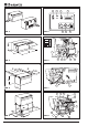
2.2 MOUNTING THE GENERATOR
Generators mod. 2500 4000 are provided
with fixing brackets,vibration dampers and petrol filter to be
placed on the fuel feed hose to the generator. Brackets
allow either suspended type "A” mounting (see fig. 3) or
traditional type "B” mounting (see fig. 4).
This is made possible by the supporting frame of the outer
casing.
Generator mod. 5500 is provided with brackets for fixing
the external seal, brackets for anchoring the unit, vibration
dampers, silencer (pos. 29 fig. 16) to be coupled to the
exhaust hose delivered as accessory AG 125 (pos. 34 fig.
16), and fuel filter which is standard installed inside the
casing (pos. 33 fig. 15). The brackets (pos. 31 fig. 16) which
allow to fix the seal (pos. 35 fig. 16) allow to mount the
generator complete with seal inside the arranged
compartment and to perfectly seal the vehicle side. The
exhaust hose can be positioned at will as shown in fig. 16
by rotating the curve inwards to either upper position or
lower position. By removing the curve, it is also possible to
directly fit the exhaust pipe by crossing the casing on its left
hand side. The prearranged floor must tolerate both the
generator mass and the vibrations due to the motion of the
vehicle ("TYPE B” mounting).
The type “A” mounting (suspended installation) offers the
following advantages: reduced overall dimensions, quick
installation, easy access for both ordinary and extraordinary
maintenance operations.
Make sure there is enough space around the generator
casing for air to pass freely (for cooling). It is also necessary
to leave at least 20 mm distance between the casing and the
surrounding parts.
If the breathing manifold is positioned behind one of the
vehicle's wheels, make sure that the tyre is prevented from
throwing
water into the casing when travelling on wet roads.
For the type “A” mounting, use the plate supports provided
to ensure that the genset is fixed securely. If type “B”
mounting is preferred (traditional installation), a watertight
compartment (fig. 2), set towards the vehicle interior and
having the dimensions given in section 1.3.3, needs to be
prearranged, with exhaust holes and air inlets drilled into the
floor and door. In addition, use an exhaust union (fig. 4),
supplied as accessory, to be fixed directly onto the generator
casing with screws or rivets. In order to prevent the exhaust
gas recycling within the compartment, place flameproof
sealing around the exhaust union.
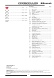
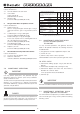
2.3 ELECTRICAL CONNECTIONS
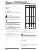
For the 230V use a standard cable with crosssection
according to table 1 below. Pass it inside the casing via the
airlead (pos. 30 fig. 7 and 9) and connect to the terminals
(pos. 17/18 fig. 6 and 14). Connect the earth wire to pos. 15.
The electrical circuit should have a relay or changeover
switch (such as accessory AG102/AG113), so as to prevent
any damage to the generator when the camper is connected
to an external mains supply (precedence is automatically
given to the mains).
2.3.1 CONNECTION OF BATTERY
RECHARGER
Use a wire with minimum crosssection according to table
1 above to connect the terminal (pos. 16 fig. 6 and 14) to
the positive lead of the battery to be recharged.
Insert the AG111 voltage regulator, or alternatively a switch,
to interrupt recharging when complete.
(See wiring diagrams, pages 55 ÷ 71).
2.3.2 CONNECTION OF STARTER BATTERY
For starting the generator, connect the positive terminal of
the vehicle's starter battery to pos. 12 fig. 6 and 14 using a
flameresistant sheathed cable having a crosssection
according to table 1 above.
The earth cable should have the same crosssection and be
connected from pos. 13 to the vehicle chassis. Make sure
that a clean, rustfree contact is made (i.e. rub down surface
if painted), and protect with grease.
2.3.3 CONNECTION OF REMOTE CONTROL
PANEL
Fix the control panel in desired position inside the vehicle
and use the individuallytested AG103 extension cable to
connect it to the genset by means of the connector pos. 14
fig. 6 and 14.
2.4 INSTALLING THE FUEL TANK
Install the fuel tank as near as possible to the generator and
if possible on the same horizontal level, or up to 30cm
below. As well as reducing the length of fuel pipe as much
as possible, make sure it is not bent or squashed. Do not
put the tank near sources of heat, and make sure that water
Mod.
Crosssection Crosssection
6 m > 6 m
mm
2
230 V mm
2
12 V
2500 2.5 2.5 10 16
4000 4 2.5 10 16
5500 4 2.5 16 25
TAB. 1
Power cables
Battery connection
Battery recharger
or workshops, Dometic Italy disclaims any responsibility
for the safety and efficient running of the generatore
accordind to the M.D. 89/392/EEC