
User Manual

2
SETUP AND CONNECTIONS
The DMX512 to Analog Converter is generally placed at the dimmer end of the control
cable. This way the control cable needs only three conductors. In retrofitting an
existing installation where the analog control cables are already in place, it may be
easier to place the Converter at the console end.
The control cable to the Converter should be designed for data communication. Cables
designed for this purpose may be called "RS-422" or "RS-485" cables or "Shielded
Twisted Pair" or "Low Capacitance Data Cable". Microphone cable is not designed for
this purpose and should not be used for control runs of over 200 feet.
TERMINATION The single most common cause of DMX512 problems is failure to
terminate the end of the control run with the proper termination resistor. If the
Converter is the final device on the control run its feed through connector should be
terminated with a 120 ohm resistor between pins 2 and 3. You may make a termination
plug by soldering a 120 ohm 1/2 watt resistor between pins 2 and 3 of a 5 pin male XLR
connector or you may purchase a terminator ready made from a Doug Fleenor Design
dealer. For more information on termination see Appendix A "Why Terminate", a paper
presented at the 1995 Lighting Dimensions International trade show.
The cabling between the Converter and the dimmers is not as critical. Any quality wire
may be used. The size or gauge of the wire is more of a mechanical consideration than
an electrical one. Almost any gauge wire will work electrically but a larger wire will be
less likely to break. Any size thicker than 22 gauge should provide reliable service.
The Converter uses 100 to 120 Volts, 50 or 60 Hertz, at less than 1/10 Amp
(approximately 6 Watts). Plug it in to a grounded outlet for maximum safety. The
Converter may have been modified to operate on 240 Volts in which case the power
cord is labeled "Wired for 240 Volts".
The Converter uses the Male 5 pin "XLR" style connector specified in the DMX512
standard for its input. A Female feed-through connector is supplied to loop the
incoming DMX signal on to other devices. There is no isolation between the input and
output DMX connectors.
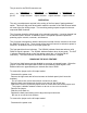
The pin outs for the 5 pin "XLR" are:
pin 1: DMX512 common
pin 2: data -
pin 3: data +
pin 4 & 5: not used (but connected to feed through connector)
There is no electrical connection between the DMX input common and the analog
output common. This is accomplished by the use of a 2500 Volt optical isolator. This
eliminates the possibility of ground loops and provides added protection for the console
against dimmer failure and electrical storm damage.
The output of the Converter is supplied on a female DB-25 connector.