
User Manual

3
The pin outs for the DB-25 connector are:
connector 1: connector 2: connector 3: connector 4:
pins 1 - 24: channels 1 - 24 channels 25 - 48 channels 49 - 72 channels 73 - 96
pin 25: output common output common output common output common
OPERATION
The only user adjustment required is the setting of the front panel "starting address"
switch. This three digit push-wheel switch reads the number of the DMX channel which
will control the first analog output. The remaining analog outputs respond to the next
sequential DMX channels.
The Converter should be left plugged in for automatic operation. It may be plugged into
a switched outlet if desired. If switched, there is no special sequence required in
powering up the console, converter, and dimmers.
The Converter is designed to hold the last levels received from the console in the event
the DMX512 signal is lost. These levels will be held until control is restored or power is
removed. All levels are reset to zero upon power up.
The front panel has three indicators. The SIGNAL indicator illuminates when a valid
DMX512 signal is present. The SIGNAL indicator flashes when in test mode. The OUT
1 indicator mimics the level on the first analog output (pin 1 of the first DB-25
connector). The PWR indicator illuminates whenever power is applied.
DISABLING THE HOLD FEATURE
The last level hold feature may be disabled by removing an internal jumper. When the
jumper is removed the outputs will be taken to zero when the DMX signal is lost.
Blackout will occur approximately one second after loss of DMX.
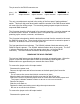
To remove the jumper on the 24 output model:
Disconnect the power cord.
Remove the right-most and left-most screws on the back panel (don't loose the
washers).
Do not remove the screws that hold the connectors in place.
Move the back panel down such that the cover may be slid off half way.
Slide off the cover to reveal the jumper which is on the same side as the power cord.
The jumper is labeled "
REMOVE JUMPER TO BLACK-OUT ON LOSS OF SIGNAL
"
Remove the jumper.
Slide the cover back on.
Replace the back panel taking care to align the output connector.
Be sure to re-use the lock washers.
To remove the jumper on the 96 output model:
Disconnect the power cord.