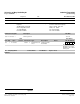
University of Mary Hardin Baylor Submittal Transmittal [For Subcontractor] Project # 1905900 Telephone: Date: January 08, 2013 Fax: 1/8/2013 Transmittal No: 0517 Jay Vanadore Transmitted To: Transmitted By: Berg Electric 4509 Freidrich Lane, Ste 105 Austin, TX 78744 Tel: 512.447.3800 Fax: 512.447.3811 Submittal Package No Description 0001 - 27 13 43.53 - 1 Qty Spec 001 1 27 13 43.
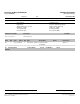
University of Mary Hardin Baylor Submittal Transmittal Project # 1905900 [For Reviewer] Telephone: Date: December 03, 2012 Fax: 12/3/12 Transmitted To: Transmittal No: 0434 Mark Olsen Transmitted By: Populous 300 Wyandotte, Suite 200 Kansas City, MO 64105 Tel: 816.329.4283 Fax: 816.329.4543 Submittal Package No Description 0001 - 27 13 43.53 - 1 Item Qty 001 1 Spec 27 13 43.53 Christine Fuentes Turner Construction Company 2001 N.
University of Mary Hardin Baylor Stadium and Student Union – UMHB Date: 12/3/12 Architect: Populous, 300 Wyandotte Suite 200, Kansas City, MO 64105 Construction Manager: Turner Construction, 2001 N. Lamar St. Suite 100, Dallas, TX 75202 Subcontractor: Berg Electric Corp., 4509 Friedrich Lane, Suite 105, Austin, TX 78144 Supplier: Manufacturer: Submittal Number: 27 23 43.53-1-001 Spec Section: 27 23 43.
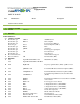
SMATV SYSTEMS Equipment List 11/16/2012 UMHB CATV 27 13 43.53 Ref Manufacturer Description Model Section 27 13 43.53 CATV 2.3 ANTENNA SYSTEM 1.14 CEF/BEF 2.4 Allowance HEADEND PART 2 PRODUCTS 2.3 ANTENNA SYSTEM A Pixel Technologies Pixel Technologies Pixel Technologies Bonder Tongue Pixel Technologies Pixel Technologies Pixel Technologies Pixel Technologies Pixel Technologies B Rhon Antenna Products C Microwave Filter Co. 2.
SMATV SYSTEMS Equipment List 11/16/2012 UMHB CATV 27 13 43.53 Ref R S T U V W X 2.
SMATV SYSTEMS Equipment List 11/16/2012 UMHB CATV 27 13 43.
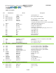
SMATV SYSTEMS Equipment List 11/16/2012 UMHB CATV 27 13 43.53 Ref Manufacturer Burtek P Q R S Liberty Wire Liberty Neutrik Neutrik Gilbert Engineering Gilbert Engineering Description Model TBD Splice Trays.
R3 G3B-2 B4B Audio Patching Systems À>`V>ÃÌÊ>`Ê ÌiÀÌ>iÌÊ*À`ÕVÌÃ Accessories Whatever the accessory you need for your audio patchbay, the quality source is ADC. Products available include patch cords, connectors and jacks, designation strip kits, and more. High-Performance Audio Patch Cords ProPatch audio patch cords are engineered for flawless performance and durability.
Video Patch Cords Ordering Information Description Ordering Number 3/04 • 1180270 Broadcast Products ST Series High-Definition Video Cords ST Standard Size Plug to Standard Size Plug Red Green Blue Black Orange Yellow Violet White 2 ft./ .61m R2V-STS G2V-STS B2V-STS BK2V-STS O2V-STS Y2V-STS V2V-STS W2V-STS 3 ft./.93m R3V-STS G3V-STS B3V-STS BK3V-STS O3V-STS Y3V-STS V3V-STS W3V-STS 4 ft./1.22m R4V-STS G4V-STS B4V-STS BK4V-STS O4V-STS Y4V-STS V4V-STS W4V-STS 6 ft./1.
MPEG 2 Standard and High Definition Encoder The mediaHUB-Pro 02 is a real-time Contribution-quality MPEG 2 Standard and High Definition encoder. It is designed to support the most demanding Contribution, ATSC, DVB and IPTV MPEG 2 Distribution applications; the Studio version of the mediaHUB-Pro 02 encodes Cable Labs VOD and DPI compliant MPEG 2 Transport Streams. The Pro’s auto-detect HD/SD-SDI video input eliminates the need for user resolution and frame rate configuration.
technical specifications TM MPEG 2 Standard and High Definition Encoder Encoder Video Profiles Encoder Audio Profiles Pro-02-S Decoder Specifications MPEG 2 SD Profile 1: Adaptive Field Frame (AFF) ISO13818-2 Dolby Digital 2.0 (AC3) dual stream encoders option. Decoder Video Output MP@ML MPEG1 Layer 2 dual stream encoders included - Confidence decode of encode via internal bus, No ASI loop MPEG 2 SD Profile 2: AFF ISO13818-2 422P@ML Dolby E, Dolby 5.1 and Dolby Digital 2.
Fiber Optic Cable Armored Tight Buffered Circular Premise Cable Armored Tight Buffered CPC Cables incorporate 4 to 144 fiber count CPC cables in a jacketed, aluminum interlocking armor. Jacketed aluminum interlocking armor provides the best balance of ruggedness, flexibility, and low weight. Flame rated armored cables with no outer jacket and flame rated armored cables with steel interlocking armor are also available.
Fiber Optic Cable Armored Tight Buffered Circular Premise Cable Mechanical Data NOMINAL DIAMETER AFL No. RISER PLENUM Fiber Count INCHES (MM) Riser WEIGHT PLENUM LBS/1000 FT LBS/1000 FT (KG/KM) (KG/KM) TENSION Riser BENDING RADIUS PLENUM Installation Long Term Installation Long Term LBS (N) LBS (N) LBS (N) LBS (N) INCHES (CM) INCHES (CM) Installation Long Term UR004481001-AIAR UP004*481001-AIAP 4 0.46 (11.8) 79 (117) 89 (132) 150 (660) 45 (198) 100 (440) 30 (132) 7.0 (17.
MODEL UNIVERSAL PANEL SYSTEM UNIVERSAL BULKHEAD PANEL SYSTEM • Design your own bulkhead • Extensive selection of connector modules • 1RU, 2RU & 3RU, 16 & 12 position available • Strain relief cable bar is standard Model WK-U216E2-Z with optional Connector Kits Model WK-U116E1-Z 2RU version shown above Model WK-U212E2-Z 2 RU Side View Model WK-U112E1-Z 6.00” [15.24] 1 RU Full List of Universal Connector Kits on the Rear www.amt.
Insulated Bulkhead Modular Bulkhead Universal Connector Kits Ordering Information Model Description Universal Panel - Panel with Cable Bar Only; no Connectors, no Adaptor Plates, no Cover Plates 3RU, 2x16 Universal Panel, Panel & Cable Bar Only, No Connectors WK-U216E3-Z 2RU, 2x16 Universal Panel, Panel & Cable Bar Only, No Connectors WK-U216E2-Z 1RU, 1x16 Universal Panel, Panel & Cable Bar Only, No Connectors WK-U116E1-Z 3RU, 2x12 Universal Panel, Panel & Cable Bar Only, No Connectors WK-U212E3-Z 2RU,
Detailed Specifications & Technical Data METRIC MEASUREMENT VERSION 1266A Multi-Conductor - Single-Pair Cable For more Information please call 1-800-Belden1 Description: 22 AWG stranded (7x30) TC conductors, polypropylene insulation, twisted pair, overall Beldfoil shield (100% coverage), 24 AWG stranded TC drain wire, PVC jacket.
Detailed Specifications & Technical Data METRIC MEASUREMENT VERSION 1266A Multi-Conductor - Single-Pair Cable Applicable Specifications and Agency Compliance (Overall) Applicable Standards & Environmental Programs NEC/(UL) Specification: CM CEC/C(UL) Specification: CM EU CE Mark: Yes EU Directive 2000/53/EC (ELV): Yes EU Directive 2002/95/EC (RoHS): Yes EU RoHS Compliance Date (mm/dd/yyyy): 01/01/2004 EU Directive 2002/96/EC (WEEE): Yes EU Directive 2003/11/EC (BFR): Yes CA Prop 65 (CJ for
Detailed Specifications & Technical Data METRIC MEASUREMENT VERSION 1266A Multi-Conductor - Single-Pair Cable Notes (Overall) Notes: Unique design features lower capacitance and greater flexibility than standard audio pair constructions. Related Documents: No related documents are available for this product Put Ups and Colors: Item # Putup Ship Weight Color 1266A 001U1000 305 MT 6.804 KG BROWN Notes Item Desc 2 #22 PP FS PVC 1266A 002U1000 305 MT 6.
Detailed Specifications & Technical Data ENGLISH MEASUREMENT VERSION 1694A Coax - Low Loss Serial Digital Coax For more Information please call 1-800-Belden1 Description: RG-6/U Type, 18 AWG solid .040" bare copper conductor, gas-injected foam HDPE insulation, Duofoil® + tinned copper braid shield (95% coverage), PVC jacket. Physical Characteristics (Overall) Conductor AWG: # Coax AWG Stranding Conductor Material Dia. (in.) 1 18 Solid BC - Bare Copper .
Detailed Specifications & Technical Data ENGLISH MEASUREMENT VERSION 1694A Coax - Low Loss Serial Digital Coax EU Directive 2003/11/EC (BFR): Yes CA Prop 65 (CJ for Wire & Cable): Yes MII Order #39 (China RoHS): Yes RG Type: 6/U Flame Test UL Flame Test: UL1666 Vertical Shaft Suitability Suitability - Indoor: Yes Suitability - Outdoor: Yes - Black only Suitability - Aerial: Yes - Black only, when supported by a messenger wire Plenum/Non-Plenum Plenum (Y/N): No Plenum Number: 1695A Elect
Detailed Specifications & Technical Data ENGLISH MEASUREMENT VERSION 1694A Coax - Low Loss Serial Digital Coax 180.000 2.570 270.000 3.170 360.000 3.690 540.000 4.600 720.000 5.380 750.000 5.500 1000.000 6.420 1500.000 7.990 2000.000 9.370 2250.000 10.010 3000.000 11.780 4500.000 14.920 Max. Operating Voltage - UL: Voltage 300 V RMS Other Electrical Characteristic 1: Impedance tested in accordance with ASTM D-4566 paragraph 43.
Detailed Specifications & Technical Data ENGLISH MEASUREMENT VERSION 1694A Coax - Low Loss Serial Digital Coax C = CRATE REEL PUT-UP. N = FINAL PUT-UP LENGTH MAY VARY -0% TO +10% FROM LENGTH SHOWN. Revision Number: 13 Revision Date: 02-22-2010 © 2012 Belden, Inc All Rights Reserved.
Detailed Specifications & Technical Data ENGLISH MEASUREMENT VERSION 1695A Coax - Low Loss Serial Digital Coax For more Information please call 1-800-Belden1 Description: RG-6/U type, 18 AWG solid .040" bare copper conductor, plenum, foam FEP insulation, Duofoil® + tinned copper braid shield (95% coverage), Flamarrest® jacket. Physical Characteristics (Overall) Conductor AWG: # Coax AWG Stranding Conductor Material Dia. (in.) 1 18 Solid BC - Bare Copper .
Detailed Specifications & Technical Data ENGLISH MEASUREMENT VERSION 1695A Coax - Low Loss Serial Digital Coax EU Directive 2003/11/EC (BFR): Yes CA Prop 65 (CJ for Wire & Cable): Yes MII Order #39 (China RoHS): Yes RG Type: 6/U Flame Test UL Flame Test: NFPA 262 CSA Flame Test: FT6 Suitability Suitability - Outdoor: No Plenum/Non-Plenum Plenum (Y/N): Yes Non-Plenum Number: 1694A Electrical Characteristics (Overall) Nom. Characteristic Impedance: Impedance (Ohm) 75 Nom.
Detailed Specifications & Technical Data ENGLISH MEASUREMENT VERSION 1695A Coax - Low Loss Serial Digital Coax 750.000 6.200 1000.000 7.300 1500.000 9.200 2000.000 10.900 2250.000 11.600 3000.000 13.700 4500.000 19.900 Max. Operating Voltage - UL: Voltage 300 V RMS Other Electrical Characteristic 1: Impedance tested in accordance with ASTM D 4566 - 05 paragraph 48.2, option 2 using a 75 Ohm fixed bridge and termination.
Detailed Specifications & Technical Data ENGLISH MEASUREMENT VERSION 1695A Coax - Low Loss Serial Digital Coax compliance date may be in stock at Belden facilities and in our Distributor’s inventory. The information provided in this Product Disclosure, and the identification of materials listed as reportable or restricted within the Product Disclosure, is correct to the best of Belden’s knowledge, information, and belief at the date of its publication.
Detailed Specifications & Technical Data ENGLISH MEASUREMENT VERSION 1815R Multi-Conductor - CMR Rated Cable For more Information please call 1-800-Belden1 Description: 22 AWG stranded (7x30) TC conductor, polyolefin insulation, individually shielded with bonded Beldfoil®, numbered/color-coded PVC jackets, jackets and shields are bonded so both strip simultaneously, overall black PVC jacket and nylon rip cord. Physical Characteristics (Overall) Conductor AWG: # Pairs AWG Stranding Conductor Material Dia.
Detailed Specifications & Technical Data ENGLISH MEASUREMENT VERSION 1815R Multi-Conductor - CMR Rated Cable 2 Red 3 Orange 4 Yellow Overall Nominal Diameter: 0.384 in. Pair Pair Color Code Chart: Color Red & Black Pair Lay Length & Direction: Lay Length (in.) Twists/ft. (twist/ft) 1.500 8.000 Mechanical Characteristics (Overall) Operating Temperature Range: -20°C To +60°C Bulk Cable Weight: 84 lbs/1000 ft. Max. Recommended Pulling Tension: 109.200 lbs. Min.
Detailed Specifications & Technical Data ENGLISH MEASUREMENT VERSION 1815R Multi-Conductor - CMR Rated Cable 56 Nominal Velocity of Propagation: VP (%) 66 Nom. Conductor DC Resistance: DCR @ 20°C (Ohm/1000 ft) 14.8 Nominal Outer Shield DC Resistance: DCR @ 20°C (Ohm/1000 ft) 11.8 Ind. Pair Nominal Shield DC Resistance @ 20 Deg. C: 14.100 Ohm/1000 ft Max. Operating Voltage - UL: Voltage 300 V RMS Max. Recommended Current: Current 1.
One Jake Brown Road Old Bridge, NJ 08857-1000 USA (800) 523-6049 • (732) 679-4000 • FAX: (732) 679-4353 www.blondertongue.com INSTRUCTION MANUAL DA-33 Wideband Amplifier Stock No. 4675A Description: The DA-33 features a wide frequency bandwidth of 0.5 MHz to 300 MHz, 36 dB gain and 18 dB of continuously variable gain control range. The DA-33 is ideal as a headend sub-channel return amplifier or on shipboard distribution systems requiring AM, shortwave and communications bands amplification.
2 DA-33 Instruction Manual The STOP sign symbol is intended to alert you to the presence of REQUIRED operating and maintenance (servicing) instructions that if not followed, may result in product failure or destruction. The YIELD sign symbol in intended to alert you to the presence of RECOMMENDED operating and maintenance (servicing) instructions.
DA-33 Instruction Manual Safety Instructions - continued ➥ o not block or cover slots and openings in the unit. These are provided for ventilation and protection from overheating. Never place the D unit near or over a radiator or heat register. Do not place the unit in an enclosure such as a cabinet without proper ventilation. Do not mount equipment in the rack space directly above or below the unit. ➥ perate the unit using only the type of power source indicated on the marking label.
4 DA-33 Instruction Manual Specifications RF Frequency Range: 0.5-300 MHz Channel Loading: 35 Channels Flatness: +/- 1 dB Full Gain: 36 dB Noise Figure: 5.5 dB Output Level: +47 dBmV Composite Triple Beat: -71 dB Cross Modulation: -55 dB Hum Modulation: -60 dB Return Loss Input: 16 dB Output: 12 dB General Power Requirements: 105 to 130 VAC, 60 Hz Operating Temperature: -40 to +65 degrees C Mechanical Dimensions (L x W x H): 11.5” x 7.125” x 3.25” Weight: 5.75 lbs.
IZhi 6XXZhhdg^Zh H6",J! ;6; ;6B M HeZX^[^XVi^dch H6",J G; I]Z H6",J ^h V kZghVi^aZ ha^YZ hl^iX] ViiZcjVidg i]Vi deZgViZh dkZg i]Z [gZfjZcXn gVc\Z d[ * id .
Product Specifications 2227K CMRL RG6 QD 1000 Material ID: 4104504/10 RG 6 Type Quad Shield Plenum Video Coaxial Cable, cream jacket, 1000 ft (305 m) reel Construction Materials Construction Type Nonarmored Center Conductor Material Copperclad steel wire Dielectric Material Foam FEP Inner Shield (Braid) Coverage 60 % Inner Shield (Braid) Gauge 34 AWG Inner Shield (Braid) Material Aluminum Inner Shield (Tape) Material Aluminum/Poly, bonded Jacket Material PVDF Outer Shield (Braid) Coverage
Product Specifications 2227K CMRL RG6 QD 1000 - Material ID: 4104504/10 Environmental Space Plenum Flame Test Method CMP Operating Temperature 40 °C to +125 °C (40 °F to +257 °F) Safety Standard cETL UL Temperature Rating 125 °C | 257 °F | ETL General Specifications Application Video Cable Type Series 6 Jacket Color Cream Product Number 2227K Center Conductor Gauge 18 AWG Center Conductor Type Solid Packaging Type Reel Mechanical Specifications Minimum Bend Radius, loaded 20 tim
Product Specifications 2287K CMRL RG11 QD 1000 Material ID: 4103304/10 RG 11 Type Quad Shield Plenum Video Coaxial Cable, cream jacket, 1000 ft (305 m) reel Construction Materials Construction Type Nonarmored Center Conductor Material Copperclad steel wire Dielectric Material Foam FEP Inner Shield (Braid) Coverage 60 % Inner Shield (Braid) Gauge 34 AWG Inner Shield (Braid) Material Aluminum Inner Shield (Tape) Material Aluminum/Poly Jacket Material PVDF Outer Shield (Braid) Coverage 40 %
Product Specifications 2287K CMRL RG11 QD 1000 - Material ID: 4103304/10 Environmental Space Plenum Flame Test Method CMP Safety Standard cETL UL Temperature Rating 125 °C | 257 °F | ETL General Specifications Application Video Cable Type Series 11 Jacket Color Cream Product Number 2287K Center Conductor Gauge 14 AWG Center Conductor Type Solid Packaging Type Reel Mechanical Specifications Minimum Bend Radius, loaded 20 times Minimum Bend Radius, unloaded 10 times Electrical Perf
QR 320 Series Cables Product Descriptions CommScope’s patented QR® coaxial cable was developed to meet the increasing demands of tomorrow’s broadband networks. QR has the highest reliability and flexibility of any Trunk and Distribution coaxial cable, low RF attenuation and an unprecedented 10 year warranty. All QR cable products offer tough polyethylene jackets and a standardized, environmentally sealed connector interface engineered for reliability and craft friendliness.
QR (JCASS) High Density Polythylene Conduit Polythylene Jacket Aluminum Outer Jacket Center Conductor Dielectric Dielectric Adhesive Flooding CommScope’s patented QR® coaxial cable was developed to meet the increasing demands of tomorrow’s broadband networks. QR has the highest reliability and flexibility of any coaxial cable, low RF attenuation and an unprecedented 10-year warranty.
Trunk & Distribution Cable Catalog Numbering Key QR 540 J CA SS - T Tracer Floodant Copper Aluminum Size PE Jacket (diameter over shield) - Suffix - J - Jacketed - CA - Copper Aluminum - SS - Miagra-Heal Flooding Compound - T - Tracer - M - Messenger - EHS - Extra High Strength 320 540 715 860 1125 QR Aerial Construction Configurations Polyethylene Jacket Aluminum Outer Conductor QR JCA Center Conductor Dielectric Dielectric Adhesive QR JCAM (Solid Messenger) Integrated Figure 8 Solid Galvanized S
QR 320 Series Cables Product Specifications Physical Dimensions Component Inches Nominal Center Conductor Diameter 0.071 Nominal Diameter Over Dielectric 0.294 Nominal Diameter Over Outer Conductor 0.320 Nominal Outer Conductor Thickness 0.013 Nominal Diameter Over jacket 0.395 Nominal Jacket Wall Thickness 0.0375 Messenger Version 0.109 Diameter of Steel Messenger 0.083 Mechanical Characteristics Minimum Bending Radius Maximum Pulling Tension Minimum Breaking Strength of Messenger (109) (.
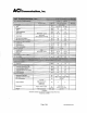
Product Specifications F1160BVR Material ID: 7736703 75 Ohm Coaxial Drop Cable, Series 11, black flame retardant PVC jacket Construction Materials Center Conductor Material Copperclad steel Dielectric Material Foam PE Inner Shield (Braid) Coverage 60 % Inner Shield (Braid) Gauge 34 AWG Inner Shield (Braid) Material Aluminum Inner Shield (Tape) Material Aluminum/Polymer/Aluminum (APA) bonded Jacket Material Fire retardant PVC Dimensions Diameter Over Center Conductor, nominal 1.626 mm | 0.
Product Specifications F1160BVR - Material ID: 7736703 Electrical Performance Frequency 5 MHz 55 MHz 83 MHz 187 MHz 211 MHz 250 MHz 300 MHz 350 MHz 400 MHz 450 MHz 500 MHz 550 MHz 600 MHz 750 MHz 865 MHz 1000 MHz Attenuation (dB/100 m) 1.25 3.15 3.87 5.74 6.23 6.72 7.38 7.94 8.53 9.02 9.51 9.97 10.43 11.97 13.05 14.27 Attenuation (dB/100 ft) 0.38 0.96 1.18 1.75 1.90 2.05 2.25 2.42 2.60 2.75 2.90 3.04 3.18 3.65 3.98 4.
Product Specifications F11SSV Material ID: 4564604 75 Ohm Coaxial Drop Cable, Series 11, black PVC jacket Construction Materials Center Conductor Material Copperclad steel Dielectric Material Foam PE Inner Shield (Braid) Coverage 60 % Inner Shield (Braid) Gauge 34 AWG Inner Shield (Braid) Material Aluminum Inner Shield (Tape) Material Aluminum/Polymer/Aluminum (APA) bonded Jacket Material PVC Outer Shield (Braid) Coverage 40 % Outer Shield (Braid) Gauge 34 AWG Outer Shield (Braid) Materi
Product Specifications F11SSV - Material ID: 4564604 Jacket Marking Feet Warranty One year Electrical Performance Frequency 5 MHz 55 MHz 83 MHz 187 MHz 211 MHz 250 MHz 300 MHz 350 MHz 400 MHz 450 MHz 500 MHz 550 MHz 600 MHz 750 MHz 865 MHz 1000 MHz Attenuation (dB/100 m) 1.25 3.15 3.87 5.74 6.23 6.72 7.38 7.94 8.53 9.02 9.51 9.97 10.43 11.97 13.05 14.27 Attenuation (dB/100 ft) 0.38 0.96 1.18 1.75 1.90 2.05 2.25 2.42 2.60 2.75 2.90 3.04 3.18 3.65 3.98 4.
F59 HEC-2 VV HEADEND CABLE 75 Ohm Coaxial Cable Drop Cable 1100 CommScope Place Hickory, NC 28603 (800) 982-1708 (828) 324-2200 Fax: (828) 324-3400 Int’l Fax: (828) 323-4989 www.commscope.com CommScope Properties, LLC All Rights Reserved PRODUCT DESCRIPTION: BONDED LAMINATED ALUMINUM TAPE, 95% BRAID, LAMINATED ALUMINUM TAPE, 95% BRAID, FLAME RETARDANT PVC JACKET CENTER CONDUCTOR: 20 AWG SILVER PLATED COPPER COVERED STEEL NOMINAL DIAMETER: 0.032” (0.
Product Specifications F6SSV Material ID: 4561004 75 Ohm Coaxial Drop Cable, Series 6, black PVC jacket Construction Materials Center Conductor Material Copperclad steel Dielectric Material Foam PE Inner Shield (Braid) Coverage 60 % Inner Shield (Braid) Gauge 34 AWG Inner Shield (Braid) Material Aluminum Inner Shield (Tape) Material Aluminum/Polymer/Aluminum (APA) bonded Jacket Material PE Outer Shield (Braid) Coverage 40 % Outer Shield (Braid) Gauge 34 AWG Outer Shield (Braid) Material
Product Specifications F6SSV - Material ID: 4561004 Jacket Marking Feet Warranty One year Electrical Performance Frequency 5 MHz 55 MHz 83 MHz 187 MHz 211 MHz 250 MHz 300 MHz 350 MHz 400 MHz 450 MHz 500 MHz 550 MHz 600 MHz 750 MHz 865 MHz 1000 MHz Attenuation (dB/100 m) 1.90 5.25 6.40 9.35 10.00 10.82 11.64 12.63 13.61 14.43 15.29 16.08 16.73 18.54 20.01 21.49 Attenuation (dB/100 ft) 0.58 1.60 1.95 2.85 3.05 3.30 3.55 3.85 4.15 4.40 4.66 4.90 5.10 5.65 6.10 6.
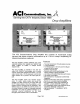
DQT1000 Digital to QAM Transcoder MQM1000 Multiplexing QAM Modulator Instruction Manual TM is a trademark of R.L. Drake LLC is a registered trademark of R.L. Drake LLC © Copyright 2007 R.L. Drake LLC P/N: 3852395C-09-2007 Printed in U.S.A.
2 Caution Statements WARNING: TO PREVENT FIRE OR ELECTRICAL SHOCK DO NOT EXPOSE TO RAIN OR MOISTURE A product and cart combination should be moved with care. Quick stops, excessive force and uneven surfaces may cause the product and cart combination to overturn.
Important Safety Instructions 1. Read Instructions—All the safety and operating instructions should be read before the product is operated. 2. Retain Instructions—The safety and operating instructions should be retained for future reference. 3. Heed Warnings—All warnings on the product and in the operating instructions should be adhered to. 4. Follow Instructions—All operating and use instructions should be followed. 5. Cleaning—Unplug this product from the wall outlet before cleaning.
4 Table of Contents / Specifications TABLE OF CONTENTS 2 3 4 5 6 Caution Statements Important Safety Instructions Table of Contents / Specifications General Description Installation and Mounting / Front Panel Controls 7 8 12 13 14 Rear Panel Controls and Connections Setup and Programming Operation / Additional Features Service / If You Need To Call For Help Warranty SPECIFICATIONS DEMODULATOR (S) DQT1000 ONLY: Input Frequency Range: Channel Plans (Menu selectable): Input Channel Bandwidth: Input RF Le
General Description 5 MQM1000 Multiplexing QAM Modulator ASI A 26.88dB ASI B 24.52dB ENTER GENERAL DESCRIPTION The R.L. Drake model DQT1000 is a professional quality, digital headend transcoder that receives one or two ATSC, or ATSC compatible MPEG2, 8VSB or QAM signals from an off air antenna or from a CATV source.
6 Installation & Mounting / Front Panel Controls INSTALLATION AND MOUNTING NOTES This equipment is designed to be installed in a standard 19” rack. All models have a built in fan to provide air movement through the unit. When the unit is mounted above or below other rack mounted equipment, a 1U space should be left between the unit and the other equipment to allow ambient air flow between the units.
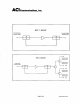
Rear Panel Connections R1 RF OUTPUT R2 EAS IN R3 DEMOD A IN R4 DEMOD B IN R5 R6 7 R7 RS232 IN ASI INPUT R9 AC POWER 120 VAC 60 Hz 30 WATTS RS232 OUT R8 DQT1000 - shown above MQM1000 - same as DQT1000 except that the MQM1000 does not have the R3 and R4 demodulator inputs or the ASI optional input. Instead it has two standard ASI inputs in place of the RF inputs on the DQT1000. The ASI inputs are type BNC female connectors.
8 Setup and Programming Programming and viewing of the various setup and operating parameters is accomplished using the front panel back lit, two line, sixteen character wide LCD along with the 4 arrow buttons and the ENTER button. The name of the parameter is on the top line of the display and the setting value is on the bottom line. To observe a certain parameter setting without intending to change its value, just use the left and right arrow buttons to navigate through the menus shown in the list.
Setup and Programming, continued QAM Mode: QAM-16A QAM-32A QAM-64A QAM-128A QAM-256A QAM-512A QAM-1024A QAM-64B QAM-256B QAM-1024B Gray Encoding: DVB (Only if ITU-A selected) DAVIC QAM Sym Rate: DQT, MQM Preset (If Preset, Sym Rate is... 5.0000 for all ITU-A, 5.0570 for QAM-64B 5.3606 for QAM-256B 5.3606 for QAM-1024B) Manual QAM Sym Rate: DQT, MQM x.xxxx M Sym/Sec (Only if Manual) Interleaver: I128,J1 (Only if ITU-B selected...
10 Setup and Programming, continued find out which MPEG programs are defined. If you wish to view the MPEG program numbers of programs that were found, follow the procedure below: VIEWING MPEG PROGRAM NUMBERS In order to see the MPEG program numbers of incoming streams, the following procedure can be followed: 1) Press the ENTER button for 2 seconds to enter program mode. Release button. Display will be flashing. 2) Press the ENTER key again and hold.
Setup and Programming, continued The third option is the BASIC MGT, VCT choice. When this selection is made, the DQT1000 or MQM1000 will build its own MGT and VCT tables from the incoming streams even if one or both of the streams do not contain these tables. This solution should satisfy all types of set top boxes but will not provide any EIT table program guide information. The STT and RRT tables from the source are passed through unchanged in the ENABLED mode and filtered out in the other modes.
12 Operation / Additional Information OPERATION - MULTIPLEXING TWO ATSC INPUTS To use the DQT1000 or the MQM1000 to multiplex two ATSC inputs, proceed as follows: 1) Connect the off-air antenna or CATV feed to the DEMOD A and DEMOD B inputs of the DQT1000 or connect the two ASI inputs to the MQM1000. For the DQT1000 the two input connectors are separate in case the two RF signals must come from different antennas or if one signal is coming from a cable system, etc.
Service / If You Need To Call For Help SERVICE INFORMATION You may contact the R.L. DRAKE Service Department for additional information or assistance by calling +1 (937) 746-6990, Monday through Friday, between 8:00 A.M. and 4:00 P.M. Eastern Time, except on holidays. You may also contact the R.L. DRAKE Service Department by E-mail at the following address: TechSupport@rldrake.com or by Telefax: +1 (937) 806-1576.
14 Warranty Three Year Limited Warranty R.L. DRAKE LLC warrants to the original purchaser this product shall be free from defects in material or workmanship for three (3) years from the date of original purchase. During the warranty period the R.L. DRAKE LLC or an authorized Drake service facility will provide, free of charge, both parts and labor necessary to correct defects in material and workmanship. At its option, R.L. DRAKE LLC may replace a defective unit.
R.L. Drake LLC 230 Industrial Drive Franklin, Ohio 45005 U.S.A. Customer Service and Parts Telephone: +1 (937) 746-6990 Telefax: +1 (937) 806-1576 World Wide Web Site: http://www.rldrake.
3400FR 1RU Passive Optical Frame 3400FR Standalone Versions (+SA option) The Evertz 3400FR passive optical frame is a powerful solution for today’s dense, modular, passive fiber optic distribution needs. The 3400FR provides flexible optical signal distribution in the form of spliiter/combiner modules that fit in the passive optical 3400FR frame. The 3400FR is a 1RU frame designed to house up to 10 splitter/combiner modules. Each module can be quad 1x2, dual 1x4 or a single 1x8 passive splitter/combiner.
3400FR 1RU Passive Optical Framee Features & Benefits • Supports 10 modules in quad 1x2, dual 1x4, single 1x8 configurations • Wideband operation from 1270nm - 1610nm • Passive splitter design for any bit rate • Fully hot swappable from front of frame without having to interrupt other signals passing through the frame • Supports single mode fiber only for high data rate and long distance applications • Angle polished connectors available (Please see ordering options below) • Available in equally distribu
Indoor Bonding Blocks Bonding Block bodies are made of high quality, extruded, corrosion resistant aluminum alloy. The “F-81” connectors are machined brass with chromate conversion coating over cadmium plating and are installed in the extruded mounting bracket. All models include grounding wire screw(s) and two (2) mounting screws.
Splice Block Product Information (G-SPB-2.00, G-SPB-2.75, G-SPB-2.75-GLU) * Broadband Products Connector Specifications Return Loss: >30 db @ 1 GHz AC Power Rating: 15 amps continuous seizing mechanism ball ended seizure screws. Listings The G-SPB-2.75 is available with UL Listing (G-SPB-2.75-GLU). The Gilbert Splice Block has been designed with superior electrical performance. The one-piece body is machined from a 6000 series aluminum alloy to minimize moisture ingress paths.
Materials and Construction of Connector Components: 6000 series aluminum alloy with gold chromate conversion coating for excellent corrosion resistance.
LED LCD TV 22LE5300 22” Class TBD” diagonal HIGHLIGHTS LED Backlighting High Definition Resolution 3M:1 Dynamic Contrast Ratio FEATURES • LED Backlighting • High Definition Resolution • 3M:1 Dynamic Contrast Ratio • Picture Wizard II (Easy Picture Calibration) • Smart Energy Saving • ENERGY STAR® Qualified • AV Mode (Cinema, Sports, Game) • Clear Voice II • ISFccc® Ready • 24P Real Cinema • USB 2.0 (JPEG, MP3, DivX HD) • DivX® HD • 2 HDMI™ 1.3 Inputs Is it a TV? Or something better? Brighter colors.
LED LCD TV 22LE5300 PANEL SPECIFICATION CONVENIENCE FEATURES Screen Size Language 4 (English/Spanish/French/Korean) 22” Class (TBD diagonal) Resolution 1366 x 768p Auto Tuning/Programming • Dynamic Contrast Ratio Channel Add/Delete • Response Time (GTG) 2.
L-Com Fiber Attenuators Premium Fiber Attenuator, LC / UPC, 5db Features • • • • • Used to attenuate Single mode fiber connectors/connections Inline design accommodates fast and easy installation Ceramic ferrules provide precise alignment Dual Wavelength (1310/1550nm) support offers multi-application flexibility Attenuating material-Ion Doped Fiber Click image(s) to zoom L-com offers an extensive line of dual wavelength (1310/1550nm) Singlemode fiber optic attenuators.
Premium Fiber Attenuator, LC / UPC, 5db - FOATLCU-05D Page 2 of 2 • Test and measurement • FTTX Diagram 2D Drawing (.pdf) 3D CAD Model (.
Catalog #817 Connectors: ConnecTecTM Termination SYstem SECTION 6 68 Connectors for 43 Cables! Designed with space-age technology, our compression connectors are revolutionary in design and exceptional in performance. With over 60 different styles of RCA, BNC and F connectors, Liberty’s ConnecTec™ Termination System offers the AV professional the broadest connector selection in the industry.
96-01003/ rev 1a / 05-21-10 HHCM Series Hinged Horizontal Cable Manager EIA/TIA Compliant EXCEPTIONAL SUPPORT & PROTECTION™ Hinged cover rackmount cable managers conceal patch cables while providing cable pass-through to equipment through the top, bottom and back of cable managers Features • Dresses cables between relay racks and other enclosures • Provides cable strain relief for more reliable connections • Multiple cable pass-throughs - top, rear, bottom and sides • Solid face conceals cables from view
HHCM Series basic dimensions All dimensions in inches unless otherwise noted [All bracketed dimensions are in millimeters]. Some dimensions given in the form of HHCM-1 / HHCM-2 2x 1.25 [32] x 4.25 [108] opening BACK VIEW HHCM-1 19.00 [483] 17.50 [446] 4x 1.50 [38] x 3.75 [95] / 4x 1.50 [38] x 4.25 [108] opening HHCM-2 TOP VIEW (HHCM-1 shown) 1.25 [32] / 1.75 [44] 3.63 [92] 18.33 [466] 1.75 [44] (one rackspace) / 3.
96-052G / rev 5e / 03-22-11 WRK Series Enclosure ® ® EIA/TIA Compliant SEISMIC CERTIFIED EXCEPTIONAL SUPPORT & PROTECTION™ The WRK Series 19” gangable enclosure accommodates large cable bundles Features • Fully welded construction provides the following weight capacities UL Listed load capacity: 2,500 lbs - Static load capacity: 10,000 lbs. Seismic certified load capacity: 900 lbs.
WRK basic dimensions REAR ViEW, Top & BoTToM 5/8” [16] dia. Ko for UHF/VHF Antenna 1/2” [13] & 3/4” [19] EKo 1” [25] & 1-1/2” [38] EKo 24.25 [616] 2.13 [514] 8.41 [214] Part # WRK-44-27 WRK-40-27 WRK-37-27 WRK-24-27 WRK-44-32 WRK-40-32 WRK-37-32 WRK-24-32 A OVERALL HEIGHT 83.13 [2111] 76.13 [1934] 70.88 [1800] 48.13 [1222] 83.13 [2111] 76.13 [1934] 70.88 [1800] 48.13 [1222] B USEABLE HEIGHT 77.13 [1959] 70.13 [1781] 64.88 [1648] 42.13 [1070] 77.13 [1959] 70.13 [1781] 64.88 [1648] 42.
96-923 / rev 5b / 04-01-11 RIB Series Riser Bases EXCEPTIONAL SUPPORT & PROTECTION™ RIB Series Riser bases provide advanced cable management Features • 1/8” thick fully welded construction • Riser bases allow for field rough-in prior to arrival of racks and enclosures • Riser bases act as a lower cable chase for passing cables between racks in multi-bay installations • Ideal for use in raised floor installations when used with optional VFEET and ANGLE / WANGLE / DANGLE / WMANGLE • Available in custom widt
D 1.75 [44] FRONT VIEW 0.437 [11.10] (rack / enclosure mounting holes 4 per bay) C A TOP VIEW RIB Series Riser Bases basic dimensions (5 Bay shown) 1.71 [43] SIDE VIEW 2x 0.375 [9.525] E laser knockout for cable entry 2.50 [63] RIB Riser Base 1.75 [44] 2 places 0.56 [14] (floor mounting holes 4 places) Middle Atlantic Products B B C E D OVERALL FLOOR MOUNTING FLOOR MOUNTING KNOCKOUT # OF RACKS DEPTH HOLES WIDTH ACCOMMODATED HOLES 17.40 [442] 1 14.87 [378] 21.80 [554] 26.
SIDE VIEW 3.00 [76] OB .343 [8.71] x 1.343 [34.112] (typ) 11.50 [292] BOTTOM VIEW A SECTION A-A 0.69 [17.
All dimensions in inches unless otherwise noted [All bracketed dimensions are in millimeters] A ANGLE / WANGLE / DANGLE BOTTOM VIEW Raised Floor Support Angles basic dimensions SIDE VIEW Knockout for cable pass-through FRONT VIEW B USED ON VFEET-1-12 MRK/VRK/VMRK 38” depth racks MRK/VRK/VMRK 38” depth racks 5 4 3 2 RACK SERIES ACCOMMODATED 1 MRK/VRK/VMRK 38” depth racks DANGLE-2-3642 DANGLE-1-3642 ANGLE-3-42 ANGLE-2-42 Part # ANGLE-1-42 59.78 [1518] 38.75 [984] 29.75 [756] 65.
96-938/ rev 5c / 08-25-10 PD Series Vertical Power Strips EXCEPTIONAL SUPPORT & PROTECTION™ PD Series Vertical Power Strips Features PD-620C-NS • Both 15 and 20 amp circuits available • Multiple termination choices: cord with plug, metal flex with tails, or J-Box PD-1215J-S • Isolated technical ground available • “Quick-clips” to enable mounting in any enclosure • Surge and spike protection, EMI filtering, and circuit breaker available PD-1020J-IG • Single and multiple circuit strips available PD-2X
Specifications for Hard-Wired PD Series Vertical Power Strips PD-2X615 NUMBER OF OUTLETS CIRCUITS NEMA OUTLET TYPE OUTLETS ACCOMMODATE (NEMA) WIRE GAUGE PD-620J-IG 6 (3 DUPLEX) (1) 20 AMP 5-20R 5-15P & 5-20P 12 PD-1020J-IG 10 (5 DUPLEX) (1) 20 AMP 5-20R 5-15P & 5-20P PD-1220J 12 (6 DUPLEX) (1) 20 AMP 5-20R PD-1220J-IG 12 (6 DUPLEX) (1) 20 AMP 5-20R PD-2X620J 12 (6 DUPLEX) (2) 20 AMP PD-2X615 12 (6 DUPLEX) (2) 15 AMP PART # ISOLATED GROUND CIRCUIT ARRANGEMENT J-BOX YES 1-1
Specifications for Corded PD Series Vertical Power Strips PD-1415C PART # NUMBER OF OUTLETS NEMA OUTLETS OUTLET ACCOMMODATE WIRE TYPE (NEMA) GAUGE CIRCUITS PD-615C 6 (3 DUPLEX) (1) 15 AMP 5-15R 5-15P PD-615C-NS 6 (3 DUPLEX) (1) 15 AMP 5-15R 5-15P 14 15 AMP CIRCUIT BREAKER NONE 1363 5-15P PD-620C-NS 6 (3 DUPLEX) (1) 20 AMP 5-20R 5-15P & 5-20P 12 20 AMP CIRCUIT BREAKER NONE 1363 5-20P PD-1015C 10 (5 DUPLEX) (1) 15 AMP 5-15R 5-15P 14 15 AMP CIRCUIT BREAKER YES 1363 & 1449
Vertical Power Strip basic dimensions Middle Atlantic Products TOP VIEW (with J-Box) TOP VIEW (without J-Box) 1.39 [36] 4.00 [102] PART # B LENGTH (FOR MODELS WITH J-BOX) PD-620J-IG 30.5 PD-1020J-IG 44 PD-1215J-S 30.5 PD-2X620J 61 PD-1220J 61 PD-2X620J 61 PART # 1.39 [36] 2.51 [64] 2.51 [64] B A LENGTH PD-615C-NS 26.5 PD-620C-NS 26.5 PD-615C 26.
Frontplattenausschnitt (Rückseite) Panel cut out (rear side)
NC3FD-L-B-1 - Neutrik Page 1 of 3 NC3FD-L-B-1 3 pole female receptacle, solder cups, black metal housing, gold contacts Universal D-size metal body XLR panel mount series. UL recognized component.
NC3MD-L-B-1 - Neutrik Page 1 of 1 NC3MD-L-B-1 3 pole male receptacle, solder cups, black metal housing, gold contacts Universal D-size metal body XLR panel mount series. UL recognized component. Features & Benefits • Robust "D" metal shell • Standardized D sized 24 mm panel cutout • Solder cups on 3 - 7 pole version Technical Information show Accessories CAS-DUMMY DBA-BL DSS-* MFD NDM SCDM SCDP-* SCDR SCDX SCM http://www.neutrik.
Frontplattenausschnitt (Rückseite) Panel cut out (rear side)
OPTICOM™ Fiber Optic Rack Mount Enclosure Part Numbers: FRME3, FRME4 INSTRUCTIONS CM271A © Panduit Corp. 2004 FRME Enclosure Parts FRME4 1 FRME Enclosure 1 FRME Kit 1 Port I.D. Label 2 EIA Enclosure Brackets FRME3 1 FRME Enclosure 1 FRME Kit 1 Port I.D. Label 2 EIA Enclosure Brackets Assembly Instructions: GROMMET CUTTING DIAGRAM 1. Determine the cable entry location on the enclosure.
INSTRUCTIONS CM271A Attach Strain Relief Clip with the #10-32 screw and nut provided. Bracket orientation for 23 inch rack Bracket orientation for flush mount on a 19 inch rack Attach the short leg of the bracket to the enclosure.
A. System Overview PHYSICAL INFRASTRUCTURE SYSTEMS B. Copper Systems Opticom ® Wall Mount Enclosures C. Fiber Optic Systems D.
FLAT PANEL MOUNTS Articulating Wall Arm For 22" to 40" LCD Screens MODELS Universal Models: Includes standard hardware (hex or Phillips) for attaching screen to mount SA740P High gloss black SA740P-S High gloss silver SCREEN ADAPTER 1. VESA® 75, 100, 200 x 100 and 200 x 200 mm compliant 2. Arm extends up to 20.18" (513 mm) from wall 3. One-touch tilt allows adjustment of +15/-5° without the use of tools 4. Up to ±90° of side-to-side swivel 5.
Pixel TECHNOLOGIES www.PixelSatRadio.com Pixel Technologies Incorporated 14828 W 6th Avenue, Unit 3B, Golden, CO 80401 Ph: 303-526-1965 Fax: 303-526-7368 © Pixel Technologies Inc. 2011 sales@PixelSatRadio.
Pixel TECHNOLOGIES www.PixelSatRadio.com Pixel Technologies Incorporated 14828 W 6th Avenue, Unit 3B, Golden, CO 80401 Ph: 303-526-1965 Fax: 303-526-7368 © Pixel Technologies Inc. 2011 sales@PixelSatRadio.
Pixel TECHNOLOGIES AM / FM Expansion Kit Model: AF Kit For use with Model: AFHD-4 AM / FM Antenna. Provides required components to add one additional AM / FM receiver to an AFHD-4 AM / FM antenna. Requires the addition of a splitter (MBS-2 or MBS-4). Kit Includes: (1) (1) (1) (2) (2) (2) AM Twin Lead Adapter F-Male to DIN Adapter Surge Protector and AM / FM Band Separator 10 dB Attenuators 20 dB Attenuators 3 ft RG-59 Cables www.PixelSatRadio.
Pixel TECHNOLOGIES Ultra Wide Band Line Amplifier for AM, FM, HD Radio, Over- the- Air TV, TV, and Satellite Radio Model: MBA-12 As opposed to standard line amps, this unit has been specially designed to amplify signals from the bottom of the AM broadcast band (500 kHz) to beyond the top of the satellite radio band (2.4 GHz).
Signal Splitters Wide Band 2-Way Passive Splitter Model: MB-2 6 ' !"# $ " : " ; 0 <" -" Wide Band 4-Way Passive Splitter (For AM/FM, HD Radio, Broadcast TV, Cable TV, and Satellite Radio) Model: MBS-4 !"# $ " % & ' & &
Distribution Accessories Model: AF Kit For use with Model: AFHD-4 AM / FM Antenna.
Custom Products DESIGN GUIDE Custom Plates and Panels www.rcicustom.
Table of Contents Custom Design & Layout Custom Graphics....................................................................................... 3 & 4 Layout Instructions Wall Plates ................................................................... 5 Wall Plate Design Template One-Gang ...................................................... 6 Wall Plate Design Template Two-Gang ...................................................... 7 Wall Plate Design Template Three-Gang ............................
Custom Design and Layout The following custom design section was created as an aid to the more common need for custom audio and video plates and panels. Blank plate and panel design templates are provided, along with drawings of several of the most commonly used connectors and devices to help you throughout the design process. HERES WHAT YOU DO. Make copies of the pages with blank plates and parts on them.
PLATE & PANEL DESIGN GUIDE GRAPHICS PLATE & PANEL DESIGN GUIDE Customize and identify your finished product with your company name or logo. GRAPHICS Graphics and text are the most obvious and notable custom option available to our customers. Professionally created and produced graphics add a pro touch to any plate or panel a touch that says quality to the end user. Use graphics in the form of engraving, silk screening, or illumination through electro luminescence.
PLATE & PANEL DESIGN GUIDE LAYOUT INSTRUCTIONS PLATE & PANEL DESIGN GUIDE STEP 1. Make copies of wall plates and full scale symbols located on pages 10 & 11. ▲ ▲ STEP 2. Trace or Paste Place the symbol page under the copy of the wall plate and trace the devices on the blank plate at the desired location OR cut out the appropriate devices from the copy of the symbol page and paste them on the blank plate at the desired location. ▲ Be sure to note device sizes and usable area of wall plate.
PLATE DESIGN WALL PLATE TEMPLATE PLATE DESIGN 2.75" X 4.5 1 Gang Wall Plate Usable Area Behind Plate PLATE DESIGNATION _____________________________ DESIGN KEY Series AL=1/8” Aluminum LT=.
PLATE DESIGN WALL PLATE TEMPLATE PLATE DESIGN 4.5" X 4.5 2 Gang Wall Plate Usable Area Behind Plate PLATE DESIGNATION DESIGN KEY Series AL=1/8” Aluminum LT=.
PLATE DESIGN WALL PLATE TEMPLATE PLATE DESIGN 6.375" X 4.5 3 Gang Wall Plate PLATE DESIGNATION _____________________________ QTY: SERIES: (select one) • AL • LT • EL AL FINISH OPTIONS: Anodize • BL • GR • CL • GL Plating • GL • NI Paint • BL • GR • IV • WH LT FINISH OPTIONS: • ST • SB • PB • MC • BZ • SZ • AZ EL FINISH OPTIONS: • BL • WH • GR LAMP COLOR: (EL only) • PW • BU • GN • BG Usable Area Behind Plate DESIGN KEY Series AL=1/8” Aluminum LT=.
PLATE DESIGN WALL PLATE TEMPLATE PLATE DESIGN 8.1875" X 4.
PLATE DESIGN PARTS TEMPLATE PLATE DESIGN FULL SCALE FOR WALL PLATES RJ-45 CAT 5 Specify solder type, feedthrough, or crimp. 801 North East Street Frederick, MD 21701 PHONE 301-620-9130 FAX 301-620-9103 PROJECT DR PN SCALE FULL 10 DRAWING NO.
PLATE DESIGN PARTS TEMPLATE PLATE DESIGN FULL SCALE FOR WALL PLATES Momentary Pushbutton SPST 903 801 North East Street Frederick, MD 21701 PHONE 301-620-9130 FAX 301-620-9103 PROJECT DR Refer to RCI Custom Catalog pages 24-27 for additional connector options. 11 PN SCALE FULL DRAWING NO.
PANEL DESIGN LAYOUT INSTRUCTIONS RACK PANEL TEMPLATE PANEL DESIGN STEP 1. Make copies of rack panels and half scale symbols on pages 18 & 19. ▲ ▲ STEP 2. Trace or Paste Usable Area Behind Panel Place the symbol page under the copy of the rack panel and trace the devices on the blank plate at the desired location OR cut out the appropriate devices from the copy of the symbol page and paste them on the blank plate at the desired location. ▲ *Be sure to note device sizes and usable area of rack panel.
PANEL DESIGN RACK PANEL TEMPLATE PANEL DESIGN Usable Area Behind Panel 1.75" X 19" EIA Rack Panel (1 Rack Space) PANEL DESIGNATION _____________________________ QTY: SERIES: (select one) • AL • LT • EL AL FINISH OPTIONS: Anodize • BL • GR • CL • GL Plating • GL • NI Paint • BL • GR • IV • WH LT FINISH OPTIONS: • ST • SB • PB • MC • BZ • SZ • AZ EL FINISH OPTIONS: • BL • WH • GR LAMP COLOR: (EL only) • PW • BU • GN • BG DESIGN KEY Series AL=1/8” Aluminum LT=.
PANEL DESIGN RACK PANEL TEMPLATE PANEL DESIGN 3.5" X 19" EIA Rack Panel (2 Rack Space) Usable Area Behind Panel PANEL DESIGNATION _____________________________ QTY: SERIES: (select one) • AL • LT • EL AL FINISH OPTIONS: Anodize • BL • GR • CL • GL Plating • GL • NI Paint • BL • GR • IV • WH LT FINISH OPTIONS: • ST • SB • PB • MC • BZ • SZ • AZ EL FINISH OPTIONS: • BL • WH • GR LAMP COLOR: (EL only) • PW • BU • GN • BG DESIGN KEY Series AL=1/8” Aluminum LT=.
PANEL DESIGN RACK PANEL TEMPLATE PANEL DESIGN 5.25" X 19" EIA Rack Panel (3 Rack Space) PANEL DESIGNATION Usable Area Behind Panel _____________________________ QTY: SERIES: (select one) • AL • LT • EL AL FINISH OPTIONS: Anodize • BL • GR • CL • GL Plating • GL • NI Paint • BL • GR • IV • WH LT FINISH OPTIONS: • ST • SB • PB • MC • BZ • SZ • AZ EL FINISH OPTIONS: • BL • WH • GR LAMP COLOR: (EL only) • PW • BU • GN • BG DESIGN KEY Series AL=1/8” Aluminum LT=.
PANEL DESIGN RACK PANEL TEMPLATE PANEL DESIGN 7" X 19" EIA Rack Panel (4 Rack Space) Usable Area Behind Panel PANEL DESIGNATION _____________________________ QTY: SERIES: (select one) • AL • LT • EL AL FINISH OPTIONS: Anodize • BL • GR • CL • GL Plating • GL • NI Paint • BL • GR • IV • WH LT FINISH OPTIONS: • ST • SB • PB • MC • BZ • SZ • AZ EL FINISH OPTIONS: • BL • WH • GR LAMP COLOR: (EL only) • PW • BU • GN • BG DESIGN KEY Series AL=1/8” Aluminum LT=.
PANEL DESIGN RACK PANEL TEMPLATE PANEL DESIGN 8.75" X 19" EIA Rack Panel (5 Rack Space) Usable Area Behind Panel PANEL DESIGNATION _____________________________ QTY: SERIES: (select one) • AL • LT • EL AL FINISH OPTIONS: Anodize • BL • GR • CL • GL Plating • GL • NI Paint • BL • GR • IV • WH LT FINISH OPTIONS: • ST • SB • PB • MC • BZ • SZ • AZ EL FINISH OPTIONS: • BL • WH • GR LAMP COLOR: (EL only) • PW • BU • GN • BG DESIGN KEY Series AL=1/8” Aluminum LT=.
PANEL DESIGN PARTS TEMPLATE PANEL DESIGN HALF SCALE FOR RACK PANELS 801 North East Street Frederick, MD 21701 PHONE 301-620-9130 FAX 301-620-9103 Momentary Pushbutton SPST 903 PROJECT DR PN SCALE HALF 18 DRAWING NO.
PARTS TEMPLATE PANEL DESIGN PANEL DESIGN HALF SCALE FOR RACK PANELS RJ-45 CAT 5 Specify solder type, feedthrough, or crimp. 801 North East Street Frederick, MD 21701 PHONE 301-620-9130 FAX 301-620-9103 PROJECT Refer to RCI Custom Catalog pages 24-27 for additional connector options. DR PN SCALE HALF 19 DRAWING NO.
CUSTOM CHASSIS PLATE & PANEL CHASSIS DESIGN GUIDE DESIGN PLATE & PANEL CHASSIS DESIGN GUIDE DESIGN CUSTOM CHASSIS MOUNTS TO 19" EIA STANDARD RACK PANEL STANDARD SIZES CH-X-Y HEIGHT = “X” PANEL SIZE 1 RU = 1 2 RU = 2 3 RU = 3 4 RU = 4 5 RU = 5 6 RU = 6 DEPTH = “Y” ACTUAL SIZE 5 = 5” 7 = 7” 9 = 9” SPECIFICATIONS WIDTH (ASSEMBLED) - 17" MATERIAL - 1/16" T6 ALUMINUM FINISH - GOLD ALODINE FRONT AND REAR PANELS MOUNT VIA #6-32 SCREWS INTO PEM-NUTS FASTENED INTO THE SIDE PANELS.
ACCESSORIES Model DRA-35S 35 mm DIN Rail Adapter Installation/Operation EN55103-1 E1-E5; EN55103-2 E1-E4 Typical Performance reflects product at publication time exclusive of EMC data, if any, supplied with product. Specifications are subject to change without notice. Step 2 Slide module into brackets. Step 3 Tighten screw to secure module. Step 1 Loosley secure brackets to DIN rail. 891-5170 Radio Design Labs Technical Support Centers U.S.A.
FLAT-PAK SERIES ™ Model FP-UBC6 Unbalanced to Balanced Converter ANYWHERE YOU NEED... • • • • • • Unbalanced to Balanced Audio 6 Channel Conversion Connectorized Audio Converter Low Noise and Distortion Cabinet, Shelf or Rack Mounting Convenience of RDL FLAT-PAKs You Need The FP-UBC6! The FP-UBC6 is part of the group of versatile FLAT-PAK products from Radio Design Labs. The unique FLAT-PAK case can be directly screwed or bolted to cabinets or shelves.
FLAT-PAK SERIES ™ Installation/Operation EN55103-1 E1-E5; EN55103-2 E1-E4 Typical Performance reflects product at publication time exclusive of EMC data, if any, supplied with product. Specifications are subject to change without notice.
STICK-ON SERIES ® Model ST-MX3 Line Level Mixer ANYWHERE YOU NEED... Audio Mixing with Up To Three Inputs Balanced or Unbalanced Inputs & Outputs To Add Additional Inputs to an Existing Mixer To Combine Signals of Different Level, Impedance, or Bal./Unbal. Configuration Low Noise and Low Distortion Performance Ground-Referenced or Floating Power You Need The ST-MX3! The ST-MX3 is part of a group of products in the STICK-ON series from Radio Design Labs.
STICK-ON SERIES ® Installation/Operation EN55103-1 E1-E5; EN55103-2 E1-E4 Typical Performance reflects product at publication time exclusive of EMC data, if any, supplied with product. Specifications are subject to change without notice.
969 Horsham Road Horsham, Pennsylvania 19044 USA The Tap Assembly to Suit Your Needs Total Tap Features • • • • • • • • • • • • • • • • The Total Tap is the only fully modular, custom configurable tap designed to serve from 2 to 48 subscribers. By using the Total Tap, You have the ability to configure the tap plates and values the way You need to, to service your customers based on Your system design. No other tap in the industry gives You this flexibility.
MODEL TXMT108-26 TXMT108-23 TXMT108-20 TXMT108-17 TXMT108-14 26 dB 23 dB 20 dB 17 dB 14 dB 11.5 dB TAP VALUE TXMT108-11T TXMT-B Blank Plate — — — 5-1000 MHz — — — BANDWIDTH COLOR CODE Blue Orange Black Purple Yellow Brown TOLERANCE ± 1.5 dB ± 1.5 dB ± 1.5 dB ± 1.5 dB ± 1.5 dB ± 1.5 dB INSERTION LOSS TYP MAX TYP MAX TYP MAX TYP MAX TYP MAX 10 - 30 MHz 0.7 0.9 0.7 1.0 1.0 1.2 2.2 2.5 3.0 3.7 Terminating 30 - 150 MHz 0.7 0.9 0.7 0.9 0.9 1.2 2.3 2.
2 & 4 Port Specifications 969 Horsham Road Horsham, Pennsylvania 19044 USA 4 Port Tap Plate Specifications MODEL TAP VALUE TXMT104-26 TXMT104-23 TXMT104-20 TXMT104-17 TXMT104-14 TXMT104-11 TXMT104-8T 26 dB 23 dB 20 dB 17 dB 14 dB 11.5 dB 8 dB — — — 5-1000 MHz — — — BANDWIDTH COLOR CODE Blue Orange Black Purple Yellow Brown Green TOLERANCE ± 1.5 dB ± 1.5 dB ± 1.5 dB ± 1.5 dB ± 1.5 dB ± 1.5 dB ± 1.
2 Port Tap Plate Specifications MODEL TAP VALUE TXMT102-26 TXMT102-23 TXMT102-20 TXMT102-17 TXMT102-14 TXMT102-11 TXMT102-8 TMXT102-4T 26 dB 23 dB 20 dB 17 dB 14 dB 11.5 dB 8 dB 4 dB — — — 5-1000 MHz — — — BANDWIDTH COLOR CODE Blue Orange Black Purple Yellow Brown Green Red TOLERANCE ± 1.2 dB ± 1.2 dB ± 1.2 dB ± 1.2 dB ± 1.2 dB ± 1.2 dB ± 1.2 dB ± 1.0 dB INSERTION LOSS TYP MAX TYP MAX TYP MAX TYP MAX TYP MAX TYP MAX TYP MAX TERMINATING 10 - 30 MHz 0.3 0.
OUTLET STRIPS Compact Series Models Compact Series General Specifications Size:8-3/4"L x 2-3/8"W x 1-1/2"H Case length (Excluding mounting tabs): 7-3/8" Maximum rating: 15A, 125VAC, 60Hz, 1875 Watts, continuous duty Outlets "U" ground Seamless Steel case with baked-on finish Components Color: Black Power Cord: 14/3 SJT, Molded Plug 603 Series * Models shown with asterisk are CSA Certified 608 Series : one outlet on end Midlength Series 24 Series General Specifications Size: 13-1/4"L x 2-3/8W x 1-1/2"H
OUTLET STRIPS DATAGARD SURGE AND NOISE SUPPRESSORS Datagard Office Series DG115-SI The popular Datagard Office Series is specifically designed to protect computers, P.O.S. terminals, sensitive instrumentation and other electronic equipment containing sensitive microprocessors.
INDUSTRIAL LINE - UPS PRODUCTS UPSTART 5-IN-1 UNINTERRUPTIBLE POWER CENTER • • • • • Maintains computer operations during power outages Electronic BookmarkTM Save and Restores your data Safeguards your system from power surges Dedicated modem protection Controls your system more conveniently The World's First 5-In1 Uninterruptible Power Center Model Number NP250 $199.00 UPSTARTTM has dual 250VA uninterruptible power outputs which support most MAC and PC systems.