
Instruction manual


20K
20K
20K
20K
UNBALANCED
16 TO 4dBu
+
-
-
BALANCED
BALANCED
UNBALANCED
-
-
1 GND
-
-
2 HIGH
-
-
3 LOW
10 TO 10dBu
+
-
-
16 TO 4dBu
+
-
-
10 TO 10dBu
+
-
-
G R O U N D
L I F T
MADE IN U.S.A.
BY
R
D C I N P U T
ON OFF
12 VDC 250 mA
+
-
-
P O W E R
OFF C + L
L
L E F T A U D I O
I N P U T
ON OFF
R I G H T A U D I O
I N P U T
(MONO)
R F O U T P U T
L I M I T I N G /
C O M P R E S S I O N
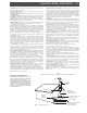
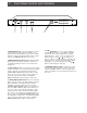
Rear Panel Controls and Connections 3
1. DC INPUT - Connect the supplied AC Adapter to this
connector. Secure AC Adapter DC cable with the
adjacent rear panel strain relief.
2. POWER ON/OFF Switch - Set this switch to the ‘ON’
position to operate the FMC 1000.
3. RF OUTPUT - This is the modulator output.
4. LIMITING/COMPRESSION SWITCH - This switch
selects the operation of the limiter. Select the proper,
or desired, setting according to the following criteria:
“OFF” - For audio sources with limiting and/or compres-
sion already applied. This setting bypasses the limiting
circuitry of the FMC 1000. With the audio source
connected, adjust the INPUT LEVEL control to a setting
at or just below the point where the (OVER) MODULA-
TION indicators light on audio peaks.
“L” - For most types of audio sources and listening
environments. This setting provides automatic limiting
on audio peaks to prevent loud bursts and to avoid
over modulation conditions which can cause distorted
audio at the receiver. With the audio source con-
nected, (for example, the output of a public address
amplifier with a person speaking at a normal level into
the microphone), adjust the INPUT LEVEL control to a
setting at the point where the (OVER) MODULATION
indicators light on audio peaks.
“C+L” - For audio sources that contain relatively low
audio levels combined with relatively high audio levels
as might be encountered when the audio output from a
public address amplifier contains audio from multiple
microphones with different persons speaking. This
setting provides automatic increasing of the low level
audio passages combined with limiting on voice peaks.
This type of audio processing can sometimes aid
intelligibility for a person receiving the signal while
located in a relatively noisy audio environment. With
the audio source connected, and the weaker audio
levels active, adjust the INPUT LEVEL control to a
setting at or just below the point where the (OVER)
MODULATION indicators light on audio peaks.
5. LEFT AUDIO INPUT - Connect monaural audio input
signals to the appropriate unbalanced or balanced
LEFT AUDIO INPUT connector. For monaural input,
program the FMC 1000 to display ‘MONO’. See Item 5;
'TUNE / Buttons' in the ‘Front Panel Controls and
Indicators' section of this manual.
For stereo input, connect an unbalanced line level left
channel stereo audio signal to the phono connector or
connect a balanced line level left channel stereo audio
signal to the 3-pin female XLR connector. The unbal-
anced phono style input and the XLR balanced input
on a given input (Left or Right) are each always active,
so audio will be fed from whichever input is being used.
Do not attempt to connect signals to both the
unbalanced and balanced connectors on a given
input (Left or Right). All inputs can be considered high
impedance (>20K Ohm). The shield connection at pin
1 of the XLR connector can be conveniently connected
to ground (GROUND LIFT = ‘OFF’) or lifted from ground
(GROUND LIFT = ‘ON’) to eliminate hum or noise as
required. For stereo input, program the FMC 1000 to
display ‘STEREO’. See ‘Front Panel Controls and
Indicators: See Item 5; 'TUNE / Buttons' in the
‘Front Panel Controls and Indicators' section of this
manual.
6. GROUND LIFT Switch - Set to the ‘OFF’ position to
connect pin 1 of both LEFT and RIGHT XLR connectors
to ground. Set to the ‘ON’ position to disconnect both
XLR connectors from ground.
7. RIGHT AUDIO INPUT - For stereo input, connect an
unbalanced line level right channel stereo audio signal
to the phono connector or connect a balanced line
level right channel stereo audio signal to the 3-pin
female XLR connector. Never connect signals to both
the unbalanced and balanced connectors on a given
input (Left or Right). The shield connection at pin 1 of
the XLR connector can be conveniently connected to
ground (GROUND LIFT = ‘OFF’) or lifted from ground
(GROUND LIFT = ‘ON’) to eliminate hum or noise as
required. For stereo input, program the FMC 1000 to
display ‘STEREO’. See Item 5; 'TUNE / Buttons' in
the ‘Front Panel Controls and Indicators' section of
this manual.
Connect a monaural audio signal to the appropriate
LEFT AUDIO INPUT connector. See Item 5: 'LEFT
AUDIO INPUT', on this page.
8. Access Hole for RF OUTPUT Level Adjustment -
The RF output level can be reduced to a value approxi-
mately 10 dB below the nominal level by adjustment of
the potentiometer. The potentiometer is tunable
through the access hole. Use a small straight-slot type
screwdriver to adjust the potentiometer, if adjustment is
necessary. Counterclockwise rotation of the potentiom-
eter decreases the output level.
1 2 3 8 4 5 6 7