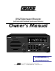
® SW2 Shortwave Receiver (with Selectable Sideband Synchronous Detector) Owner's Manual SW2 Shortwave Receiver MEM + 60 + 40 + 20 S9 AM SYNC LSB USB METER POWER RF GAIN VFO TUNING kHz 1 2 3 MEM 4 5 6 AM SYNC 7 8 9 SSB 0 CLEAR VOLUME Downloaded by Amateur Radio Directory www.hamdirectory.info ® is a registered trademark of the R. L. Drake Company © Copyright 1997 R. L. Drake Co. P/N: 3851332B-4-1997 Printed in the U. S. A.
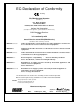
EC-Declaration of Conformity marking We, Manufacturer/Importer (Full address) R. L. Drake Company 230 Industrial Drive Franklin, Ohio 45005 United States of America declare that the product (description of the apparatus, system, installation to which it refers) SW2 Shortwave Receiver 1292 is in conformity with Council Directive 89/336/EEC (EMC Directive) Standards to which conformity is declared: EN55013:06.90+A12/08.
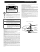
Important Safeguards WARNING: TO PREVENT FIRE OR ELECTRICAL SHOCK DO NOT EXPOSE THIS PRODUCT'S AC ADAPTOR TO RAIN OR MOISTURE ¡WARNING! RISK OF ELECTRIC SHOCK DO NOT OPEN WARNING: TO REDUCE THE RISK OF ELECTRIC SHOCK, DO NOT REMOVE COVER OF AC ADAPTOR NO USER-SERVICABLE PARTS INSIDE REFER SERVICING TO QUALIFIED PERSONNEL An appliance and cart combination should be moved with care. Quick stops, excessive force and uneven surfaces may cause the appliance and cart combination to overturn.
ii This page left intentionally blank
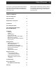
Table of Contents Please carefully read the Owner's Manual in order to take advantage of the many interesting features that will provide enjoyable listening to radio broadcasts around the world. Thank you for purchasing an SW2 Shortwave Receiver. This receiver has been designed and manufactured to high quality standards, and will provide reliable operation for many years.
iv Specifications / Optional Accessories Frequency Range: 100 - 30,000 kHz Less than 2.0 µV, typical 100 - 30,000 kHz Sensitivity: AM (10 dB S+N/N) (1000 Hz, 30% Mod) To nearest 0.1 kHz Readout Accuracy: Selectivity: AM 6 kHz @ -6 dB, less than 12 kHz @ -60 dB 2.3 kHz @ -6 dB, less than 5 kHz @ -60 dB Selectivity: SSB IF Frequency: 1st IF: 2nd IF: External Speaker: 1/4" mono type Supplied AC Adaptor Wall Transformer: Input: 120 VAC ±10%, 60 Hz, 15 Watts Output: 12 VAC at 1.67 A maximum Less than 0.
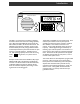
Introduction 1 SW2 Shortwave Receiver MEM + 60 + 40 + 20 S9 AM SYNC LSB USB METER POWER RF GAIN VFO TUNING kHz 1 2 3 MEM 4 5 6 AM SYNC 7 8 9 SSB 0 CLEAR VOLUME The SW2 is a microprocessor controlled, synthesized, shortwave receiver with continuous coverage capability from 100 kHz through 30000 kHz which includes the AM broadcast, Amateur, CB and shortwave bands. The SW2 offers good sensitivity, selectivity, dynamic range and features that permit easy tuning of desired stations.
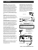
2 Front Panel Description 6 4 SW2 Shortwave Receiver MEM + 60 + 40 + 20 S9 AM SYNC LSB USB METER POWER RF GAIN VFO TUNING kHz 1 2 3 MEM 4 5 6 AM SYNC 7 8 9 SSB 0 CLEAR VOLUME 5 3 1) Tuning (VFO)*- The tuning wheel and the / buttons are the primary tuning controls of the receiver. Clockwise rotation of the dial increases frequency in 50 Hz steps and counterclockwise rotation decreases frequency in 50 Hz steps. The / buttons increment and decrement the frequency in 5 kHz steps.
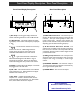
Front Panel Display Description / Rear Panel Description Front Panel Display Description 1 2 3 Rear Panel Description 3 1 2 3 4 5 MEM + 60 + 40 ANTENNA + 20 50 50 EXTERNAL SPEAKER PO WER INPUT GND S9 SYNC AM 7 LSB USB 6 POWER METER 5 4 /8 CAUTION: BRIDGEAMPLIFIER OUTPUT, DO NOT GROUND EITHER SPEAKER LEAD. 4 1) Bar Graph - This bar graph display indicates the relative received signal level in S-units and dB above S9.
4 Installation UNPACKING - Carefully remove the SW2 and included AC Adaptor wall transformer from the shipping carton and examine them for evidence of damage. If any damage is noted, immediately contact the transportation company responsible for delivery or return the unit to the dealer from whom it was purchased. Keep the shipping carton and all packing material for the transportation company to inspect.
Installation, continued RANDOM LENGTH WIRE ANTENNA INSTALLATION For general broadcast and shortwave listening, an outside random-length wire antenna can be used. Figure 3 shows a typical random-length wire antenna installation. The length of the wire may be from 30 to 100 feet. Attach and solder the lead-in to one end of the antenna. Connect the other end of the lead-in wire to the 50Ω screw terminal on the rear panel of your receiver.
6 Getting Started SW2 Shortwave Receiver MEM + 60 + 40 + 20 S9 AM SYNC LSB USB METER POWER RF GAIN VFO TUNING kHz 1 2 3 MEM 4 5 6 AM SYNC 7 8 9 SSB 0 CLEAR VOLUME RF GAIN VOLUME NUMERIC KEYPAD POWER TUNING BUTTONS TUNING WHEEL FIGURE 4 GENERAL OPERATING INFORMATION This receiver is easy to use. Please take a few moments to read through this section and familiarize yourself with general operating information. GETTING STARTED 1.
Getting Started, continued Example 2: 29660 kHz Press 2 , 9 , 6 , ** 6 , 0 ** When the maximum of 5 digits are entered, the receiver will automatically enter the frequency as soon as the last digit is pressed. TUNING BUTTONS and TUNING WHEEL Tuning to a desired frequency can also be accomplished by pressing the / Tuning buttons and/or turning the Tuning wheel. The frequency will change in 5 kHz increments with the / Tuning buttons, and will change in 50 Hz increments when turning the Tuning wheel.
8 Getting Started, continued AM SYNCHRONOUS OPERATION, continued If interference is present, press the SSB button to select the sideband with the least interference. When AM/SYNC has been activated, moving the main tuning knob will cause the SYNC circuit to momentarily disengage (indicated by SYNC flashing), then back on again when tuning has stopped. AM SYNC will not operate properly on intermittent transmissions such as those encountered on CB radio bands, for example.
Memory Functions This receiver contains 100 memories (00-99) that can be used to store and recall commonly monitored frequencies. The following operating parameters are also stored with any memory channel: 1) Frequency 2) Mode 3) Synchronous Detector NOTE: Some of the 100 memory channels are factory programmed to help the user get started.
10 Troubleshooting TROUBLESHOOTING PROBLEM PROBABLE CAUSE SOLUTION No front panel display A) No power applied either by AC Adaptor or DC source. A) Check that AC Adaptor cable or DC cable is properly connected to the rear panel POWER INPUT connector. Check that the AC Adaptor is plugged into a source of nominal 120 VAC power source. B) Check the AC Adaptor and replace if defective. Check DC power source, fuse and cable. C) Press the button for a frequency display.
Service Information / If You Need To Call For Help SERVICE INFORMATION You may contact R. L. DRAKE Service Department for additional information or assistance by calling (513) 746-6990, Monday through Friday, 8:00 A.M. 5:00 P.M. EST, except on holidays. You may also contact the R. L. DRAKE Service Department by E-mail at the following address: service@rldrake.com or by Telefax: +1 (513) 743-4576.
12 This page left intentionally blank
Warranty 13 One Year Limited Warranty R.L.DRAKE COMPANY warrants to the original purchaser this product shall be free from defects in material or workmanship for one (1) year from the date of original purchase. During the warranty period the R.L.DRAKE COMPANY or an authorized Drake service facility will provide, free of charge, both parts and labor necessary to correct defects in material and workmanship. At its option, R. L. Drake Company may replace a defective unit.
® R.L. DRAKE COMPANY 230 INDUSTRIAL DRIVE FRANKLIN, OHIO 45005 U. S .A. CUSTOMER SERVICE AND PARTS TELEPHONE: +1 (513) 746-6990 TELEFAX: +1 (513) 743-4576 WORLD WIDE WEB SITE: http://www.rldrake.com Downloaded by Amateur Radio Directory www.hamdirectory.