
Owner`s manual


4 Installation
GND
A N T E N N A
P O W E R
I N P U T
+12 VDC
OR
12 VAC
1.5 A
- - -
MADE IN U. S. A.
BY ®
50
50
SERIAL #
E X T E R N A L
S P E A K E R
4 /8
CAUTION: BRIDGE-
AMPLIFIER OUTPUT,
DO NOT GROUND
EITHER SPEAKER LEAD.
P O W E R
I N P U T
+12 VDC
OR
12 VAC
1.5 A
- - -
E X T E R N A L
S P E A K E R
4 /8
CAUTION: BRIDGE-
AMPLIFIER OUTPUT,
DO NOT GROUND
EITHER SPEAKER LEAD.
UNPACKING - Carefully remove the SW2 and
included AC Adaptor wall transformer from the
shipping carton and examine them for evidence of
damage. If any damage is noted, immediately contact
the transportation company responsible for delivery or
return the unit to the dealer from whom it was
purchased. Keep the shipping carton and all packing
material for the transportation company to inspect.
The original carton and packing material should be
retained for repackaging should it be necessary to
return the receiver. Inspect the packing material for
any accessories or printed material before storing the
box.
LOCATION - Location is not critical. For fixed
locations, the SW2 should be operated from the AC
Adaptor. Keep curtains and other flammable material
away from direct contact with the AC Adaptor to avoid
overheating the transformer which could result in
failure or fire.
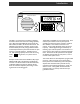
FIXED INSTALLATION - After unpacking the unit,
connect the antenna system to the appropriate antenna
input. Connect system ground to the screw terminal
marked GND. Plug the output cable of the AC
Adaptor into the POWER INPUT connector on the
rear panel of the receiver. Plug the AC Adaptor into a
source of 120 VAC, 60 Hz power. Refer to Figure 2
for the diagram of a typical fixed installation.
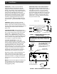
ANTENNA REQUIREMENTS - Basic type
Connect a single wire lead-in to the 50 Ohm screw
terminal on the rear panel of the receiver. This lead-
in wire and antenna can simply be one end of the
supplied 30 feet piece of wire. The wire can be
distributed along an attic, out the window, or across
the room, for example. The end that connects to the
50 Ohm screw terminal must have its insulation
stripped back so that a good electrical connection is
made between the wire and the screw terminal.
Alternatively, a 50 Ohm coaxial cable feedline from a
dipole, vertical or beam type antenna should be
connected to the rear panel 50 Ohm SO-239 coaxial
type antenna connector. A mating PL-259 connector
on the receiver end of the coaxial cable is required, in
this case.
NOTE: Disconnect the AC Adaptor and antenna wire
from the receiver if the unit will not be used for an
extended period of time or if a storm containing
damaging lightning is likely.
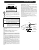
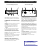
OPERATION FROM 12 VDC VEHICLE SUPPLY -
Observe proper polarity connection between the
vehicle lighter or accessory socket and the coaxial DC
power plug (5.5 mm O.D., 2.1 mm I.D.) which is
intended for connection to the SW2 power socket.
The exposed outside metal shell of the 5.5 mm power
plug is the "-" (Negative) connection to the SW2 rear
panel connector socket. The inside metal contact
surface is the "+" (Positive) connection to the SW2
rear panel connector socket.
Vehicle
12 VDC
accessory
connection
---------- ---------
--
--
---
Standard 12 VDC Power Plug (fused)
(or approved accessory connector)
Coaxial DC Power Plug (-) Outside Metal 5.5mm O.D.
(+) Inside Metal 2.1mm I.D.
FIGURE 1 - PROPER WIRING POLARITY AND
FUSING DIAGRAM
Fuse 5 A (SFE TYPE)
WARNING: Stay away from power lines when
you install this, or any, antenna. Make certain
that the antenna cannot come in contact with
power lines.
LOW IMPEDANCE
ANTENNA
SW2 Rear Panel
Run a wire the length of the
attic. DO NOT PLACE WIRE
NEAR POWER LINES.
Disconnect antenna from
receiver if there is a long time
period between uses.
- OR -
FIGURE 2 - BASIC ANTENNA CONNECTIONS
PL-259
CONNECTOR
SUPPLIED WIRE
ANTENNA (30 FT)
THIS END MUST HAVE
INSULATION REMOVED