
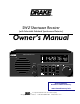
Owner`s manual


AM
METER
SYNC LSB
USB
POWER
MEM
+ 60
+ 40
+ 20
S9
Front Panel Display Description / Rear Panel Description 3
1 2 3 4 5
GND
A N T E N N A
P O W E R
I N P U T
+12 VDC
OR
12 VAC
1.5 A
- - -
MADE IN U. S. A.
BY ®
50
50
SERIAL #
E X T E R N A L
S P E A K E R
4 /8
CAUTION: BRIDGE-
AMPLIFIER OUTPUT,
DO NOT GROUND
EITHER SPEAKER LEAD.
1 2 3
7 6 5 4
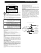
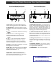
1) 50 Ohm SO-239 Connector - This antenna input is a
50 Ohm, S0-239 coaxial input requiring a mating PL-259
connector. This input would typically be used as the
primary antenna input. Antennas such as dipoles, trap
dipoles, verticals and beams will provide the best results
depending upon the desired receiving frequency.
2) 50 Ohm Antenna Wire Screw Terminal - This
antenna input is a 50 Ohm screw terminal type requiring
bare wire from an antenna to be compressed under the
screw heads. An antenna such as a random-length wire will
provide the best results.
3) GND (ground) Connection - This is the point from
which the receiver may be grounded in order to improve
reception when using, for example, a random length
antenna.
4) EXTERNAL SPEAKER - This connector accepts a
1/4" stereo/mono audio jack. Reception is monaural only.
Do not ground either speaker lead.
5) POWER INPUT - This is for the AC adaptor.
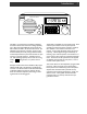
1) Bar Graph - This bar graph display indicates the
relative received signal level in S-units and dB above S9.
2) 6 Digit Readout - This display indicates the operat-
ing frequency of the receiver. The frequency is displayed
in 'kHz'.
3)
MEM
- This annunciator indicates current memory
location from 00 to 99. MEM will light when the
receiver enters the memory mode. Refer to the
'MEMORY FUNCTIONS' section of this manual.
4)
METER
- Lights in the VFO mode to indicate the
Shortwave band designators that define a range of
frequencies for each band. Refer to the "Shortwave
'Meter' Band Designator Entry" section of this manual.
5) POWER - Indicates that the AC Adaptor is connected
and plugged into an AC wall outlet.
6) LSB / USB - LSB Indicates that the Lower sideband
mode of detection is on. USB indicates that the Upper
sideband mode of detection is on.
7) AM / SYNC - Indicates that the AM mode of
reception is on. If SYNC is also illuminated, then the
synchronous AM mode of detection is on. With SYNC
active, select USB or LSB for best reception.
Front Panel Display Description Rear Panel Description
Downloaded by
Amateur Radio Directory
www.hamdirectory.info