Master flow DC2496 HIGH RESOLUTION ANALOGUE TO DIGITAL CONVERTER COPYRIGHT This manual is copyrighted 8 1999 by Drawmer Electronics, Ltd. With all rights reserved.
ONE YEAR LIMITED WARRANTY Drawmer Electronics Ltd., warrants the Drawmer DC2496 high resolution analogue to digital converter to conform substantially to the specifications of this manual for a period of one year from the original date of purchase when used in accordance with the specifications detailed in this manual.
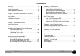
CONTENTS Warranty . . . . . . . . . . . . . . . . . . . . . . . . . . . . . . . . . . . . . . . 2 Contents . . . . . . . . . . . . . . . . . . . . . . . . . . . . . . . . . . . . . . . 3 Safety Consideration . . . . . . . . . . . . . . . . . . . . . . . . . . . . . 4 Radio Frequencies Statement . . . . . . . . . . . . . . . . . . . . . . 4 Chapter 1 - DC2496 Hi Resolution A/D Converter Introduction . . . . . . . . . . . . . . . . . . . . . . . . . . . . . . . . . . . . 5 Key Features . . . . . . . . . . .
DRAWMER DC2496 For the USA HIGH RESOLUTION ANALOGUE TO DIGITAL CONVERTER FEDERAL COMMUNICATIONS COMMISSION RADIO FREQUENCY INTERFERENCE STATEMENT This equipment has been tested and found to comply with the limits for a Class B digital device, pursuant to Part 15 of the FCC Rules. These limits are designed to provide reasonable protection against harmful interference in a residential installation.
Chapter CHAPTER 1 DRAWMER DC2496 HIGH RESOLUTION ANALOGUE TO DIGITAL CONVERTER INTRODUCTION The Drawmer DC2496 is an extremely sophisticated, high resolution analogue to digital converter designed for use in demanding recording and broadcast applications. Both analogue (balanced XLR) and digital (AES/ EBU, S/PDIF, ADAT 8 Channel light pipe and TDIF 8 Channel) I/O is provided as standard.
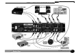
Chapter 1 DC2496 HI RES A/D CONVERTER AUDIO CONNECTIONS Analogue Inputs The inputs and outputs to the DC2496 are electronically balanced and would normally be connected to your system via a patchbay. Should unbalanced operation be required, simply ground pin 3 on the XLR connectors. If earth loop hum problems are encountered, do not disconnect the mains earth but instead, try disconnecting one end of the signal screen on the cables connecting the DC2496 to the patchbay.
Chapter 1 DC2496 HI RES A/D CONVERTER INSTALLATION AND CONNECTION GUIDE 7
Chapter 2 DC2496 BASIC EFFECTS BASIC EFFECTS CHAPTER 2 Input Signal Limiter Word Resolution Dither INPUT SIGNAL shows the selected input source. This signal is also indicated on the rear panel by lighting the selected signal Green LED. The WORD CLOCK must be set to the appropriate source otherwise clicks, pops or even loud white noise may be heard. When setting up for a new signal source firstly select the mode for RECORD or PLAY (each mode has its own set of input, Limiter, Word Res etc.
Chapter 2 Sample Rate / Ext Word Clock Replay Track Mode SAMPLE RATE selects the required highly accurate internal crystal controlled dual PLL clock signal. This can be 44.1, 48, 88.2,96k or EXT which can use an external Word Clock signal. EXT WORD CLOCK selects the source for the word clock (indicated by a yellow LED on the rear panel). It must be within the range 30kHz to 100kHz.
Chapter OPERATION 3 Setup System using Internal Sine Wave Generator CHAPTER 3 OPERATION Use the internal sine wave generator to confirm output signals and to identify left/right channels. A 100Hz, 1kHz or 10kHz internally generated sine wave at -40dB, -20dB or 26dB to -6dB variable will be sent to all outputs. When the input signal button is pressed the setup tone stops.
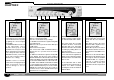
Chapter WORD CLOCK REAR PANEL - BOTTOM ROW MAIN DIGITAL OUTPUTS DIGITAL I/O SPDIF SPDIF/AES AES ADAT TDIF-1 ADAT TOGGLE DIGITAL INPUTS WORD SPDIF CLOCK AES WORD CLOCK OPERATION 3 REAR PANEL - TOP ROW AUX DIGITAL OUTPUTS ANALOGUE OUTPUTS SPDIF SPDIF/AES AES SAMPLE WORD LEFT MAX RIGHT TOGGLE RATE RES LEVEL ANALOGUE INPUTS LEFT MAX RIGHT LEVEL 16 Bit 20 Bit word clock Not output connected AES sine wave output sine output on all 8 tracks sine wave will be output on all 8 tracks Not active Not
Chapter 3 OPERATION 96K 24Bit Recording and Replay OPERATION 96K 24Bit A/D conversion with monitor speakers recording and replaying, 8 Track digital tape recorders, DAT and 24Bit 96K hard disk recorder, also recording 44.1K 16 Bit to Mini-disc, all simultaneously. COMMENTS 1) Ensure that the A/D input signal does not light the overload leds - analogue clipping will occur. Reduce the mixer output level as required.
Chapter WORD CLOCK REAR PANEL - BOTTOM ROW MAIN DIGITAL OUTPUTS DIGITAL I/O SPDIF SPDIF/AES AES ADAT TDIF-1 ADAT TOGGLE DIGITAL INPUTS WORD SPDIF CLOCK AES WORD CLOCK OPERATION 3 REAR PANEL - TOP ROW AUX DIGITAL OUTPUTS ANALOGUE OUTPUTS SPDIF SPDIF/AES AES SAMPLE WORD LEFT MAX RIGHT TOGGLE RATE RES LEVEL ANALOGUE INPUTS LEFT MAX RIGHT LEVEL 16 Bit 20 Bit to Tascam Not word clock connected in AES to Hard Disk Recorder to ADAT Recorder to Tascam Recorder Not active Not active Not active No
Chapter 3 OPERATION 48K 24Bit Recording and Replay OPERATION 48K 24Bit A/D conversion with monitor speakers recording and replaying, 8 Track digital tape recorders, DAT and 24Bit 48K hard disk recorder, also recording 44.1K 16 Bit to Mini-disc, all simultaneously. COMMENTS 1) Ensure that the A/D input signal does not light the overload leds - analogue clipping will occur. Reduce the mixer output level as required.
Chapter WORD CLOCK REAR PANEL - BOTTOM ROW MAIN DIGITAL OUTPUTS DIGITAL I/O SPDIF SPDIF/AES AES ADAT TDIF-1 ADAT TOGGLE DIGITAL INPUTS WORD SPDIF CLOCK AES WORD CLOCK OPERATION 3 REAR PANEL - TOP ROW AUX DIGITAL OUTPUTS ANALOGUE OUTPUTS SPDIF SPDIF/AES AES SAMPLE WORD LEFT MAX RIGHT TOGGLE RATE RES LEVEL ANALOGUE INPUTS LEFT MAX RIGHT LEVEL 16 Bit 20 Bit to Tascam Not word clock connected in AES to Hard Disk Recorder to ADAT Recorder to Tascam Recorder Not active Not active Not active No
Chapter 3 OPERATION Multi-Track Copy OPERATION Digitally copy ADAT to TDIF or TDIF to ADAT 44.1/48K or 88.2/96K recordings. Also reduce 48K 24Bit triple tracks to 48K 16 Bit stereo with optimum dither, without using sample rate conversion. COMMENTS 1) When the TDIF plug is inserted into the rear of the DC2496 the main digital output word clock BNC is only suitable for TDIF word sync input. 2) If digital gain is applied with the limiter off then unpleasant digital distortion can occur on peaks.
Chapter WORD CLOCK REAR PANEL - BOTTOM ROW MAIN DIGITAL OUTPUTS DIGITAL I/O SPDIF SPDIF/AES AES ADAT TDIF-1 ADAT TOGGLE DIGITAL INPUTS WORD SPDIF CLOCK AES WORD CLOCK OPERATION 3 REAR PANEL - TOP ROW AUX DIGITAL OUTPUTS ANALOGUE OUTPUTS SPDIF SPDIF/AES AES SAMPLE WORD LEFT MAX RIGHT TOGGLE RATE RES LEVEL ANALOGUE INPUTS LEFT MAX RIGHT LEVEL 16 Bit 20 Bit to Tascam Not word clock connected in AES use if required not active to Tascam Recorder ADAT optical input & word clock Not active Not a
Chapter 4 SPECIAL OPERATION NOTES CHAPTER 4 HELPFULL HINTS Recording Hi-Resolution ‘Bit splitting’ tracks on a Digital Tape Recorder (ADAT or TDIF) When recording Triple (48k) or Hex (96k) Hi-Resolution tracks to tape the SRC (upper) AES & SPDIF digital outputs will monitor tracks 7/8 @ 20 or 16bit resolution depending on the rear panel push switch. When TDIF ‘D’ plug is inserted the DC2496 BNC Word Clock output will be phase shifted by 90 degrees at a rated 44.1k @ 88.2k and 48k @ 96khz.
Chapter CHAPTER 5 DC2496 INFORMATION SOFTWARE UPGRADES Periodically there may be additions to the DC2496 software that will be made available. In order to carry out a software upgrade to the DC2496 the following parts will be required: 486 or better PC computer running Win95 or late. Cable - RS232 9 pin to RS232 9 pin. Connected to Com 1 on the P.C. and into the RS232 port on the rear of the DC2496. DRAWMER ‘Masterflow DC2496 upgrade’ software - available free from our web site.
Chapter 6 GENERAL INFORMATION CHAPTER 6 GENERAL INFORMATION IF A FAULT DEVELOPS For warranty service please call Drawmer Electronics Ltd. or their nearest authorised service facility, giving full details of the difficulty. A list of all main dealers can be found on the Drawmer webpages. On receipt of this information, service or shipping instructions will be forwarded to you. No equipment should be returned under the warranty without prior consent from Drawmer or their authorised representative.
Chapter 7 DC2496 DATA CHAPTER 7 DC2496 DATA SPECIFICATION Analogue Input Connectors Impedance Max. Input Level Input CMR A to D Conversion Dynamic Range Crosstalk Sample Rate Digital Inputs and Outputs XLR Balanced (Pin 2 Hot) 10 KΩ +24 dBu Better than -50dB 24 Bit A/D >129dBFs A Weighted at 48KHz -100dB @1kHz -90dB@10kHz 44.1, 48, 88.2, 96kHz, EXT Analogue Output Connectors Impedance Max.
Chapter 7 DC2496 DATA BLOCK DIAGRAM Ref:1v02 A 30-09-04 22