DL221 OPERATORS MANUAL and DL120 CONTENTS SAFETY CONSIDERATIONS page 1 INTRODUCTION page 2 INSTALLATION page 3 CONTROL DESCRIPTIONS page 4 OPERATION page 6 TECHNICAL SPECIFICATION page 8 h DRAWMER ELECTRONICS LTD.
COPYRIGHT This manual is copyrighted © 1990 by Drawmer Electronics, Ltd. With all rights reserved. Under copyright laws, this manual may not be duplicated in whole or in part without the written consent of Drawmer. ONE YEAR LIMITED WARRANTY Drawmer Electronics Ltd., warrants the Drawmer DL221 audio processor to conform substantially to the specifications of this manual for a period of one year from the original date of purchase when used in accordance with the specifications detailed in this manual.
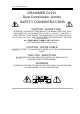
1 DL221 OPERATORS MANUAL DRAWMER DL221 Dual Compressor Limiter SAFETY CONSIDERATIONS CAUTION - MAINS FUSE TO REDUCE THE RISK OF FIRE REPLACE THE MAINS FUSE ONLY WITH THE SAME TYPE, WHICH MUST BE A CLASS 3, 230 VOLT, TIME DELAY TYPE, RATED AT 63mA WHERE THE MAINS INPUT VOLTAGE SWITCH IS SET TO 230 VOLTS AC. AND 125mA WHERE THE MAINS INPUT VOLTAGE IS 115 VOLTS AC. ALL FUSES MUST COMPLY WITH IEC127-2. THE FUSE BODY SIZE IS 20mm x 5mm.
2 DL221 OPERATORS MANUAL INTRODUCTION The DL221 is a Dual Compressor/Limiter combining ease of operation with flexible performance, low noise and low distortion. The DL120 is a Modular, Single Compressor/Limiter offering identical performance.
3 DL221 OPERATORS MANUAL INSTALLATION The DL221 is designed for standard 19" rack mounting and occupies 1U of rack space. Avoid mounting the unit directly above power amplifiers or power supplies that radiate significant amounts of heat. Fibre or plastic washers may be used to prevent the front panel becoming marked by the mounting bolts.
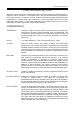
4 DL221 OPERATORS MANUAL CONTROL DESCRIPTION Both channels of the DL221 are identical and may be used completely independently or linked for stereo operation. In the linked mode, only the left hand channel controls are functional and serve as master controls, though the channel bypass switches remain independent.
DL221 OPERATORS MANUAL 5 LED BAR DISPLAY is a dual function facility which measures output level (input level if bypass is selected) or gain-reduction, selectable by the display switch. NB i. ii. The VU meter and threshold controls are calibrated to show 0VU at +4dB In the gain reduction mode, all the red LED’s are very slightly illuminated at all times. This is quite normal and does no indicate a fault condition.
6 DL221 OPERATORS MANUAL OPERATION Having connected signal inputs and outputs as required, set the unit as followsThreshold, Ratio, Attack, Release Output Gain Display Switch Output Switch Peak Limit Stereo Link Display 1. 2. 3. 4. 5. 6. - Anti clockwise 0 dB VU Bypass Off Off VU Adjust input signal level on preceding equipment to show 0 dB on display, peaking to +2. Change output switch to ‘norm’ and display switch to GR.
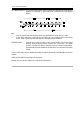
DL221 OPERATORS MANUAL 7 DL 120 CONNECTION DETAILS 1 2 3 4 5 6 7 8 9 - +24V !24V 0V 0V - Stereo link. This point should be connected to pin 9 on another DL120 via a switch for stereo operation. Alternatively, connect both pin 9' s to two points on the patch bay and link them for stereo. 19 20 21 22 23 24 25 26 27 - Output - Ov Side-chain send Side-chain return Ov Input - Ov If side-chain access is not required, pins 22 and 23 must be shorted, either at the rack or patch bay.
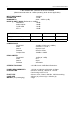
8 DL221 OPERATORS MANUAL TECHNICAL SPECIFICATIONS (Measurements taken at +4dBu operating level where applicable) INPUT IMPEDANCE 10KOhm HEADROOM +18dB BANDWIDTH 20Hz - 30KHz (1dB) NOISE @ UNITY GAIN (Referred to +4dBm) Wideband !85dB 22Hz-22KHz !90dB CCIR ARM !91dB IEC A !93dB DISTORTION 100Hz 1KHz 10KHz Unity gain +4dBm Input 0.02% 0.02% 0.02% +14dBm input 20dB GR. 0.05% 0.04% 0.