
Manual

DL221 OPERATORS MANUAL
7
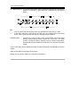
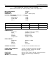
DL 120 CONNECTION DETAILS
1 - +24V
2 - !24V
3 - 0V
4 - 0V
5
6
7
8
9 - Stereo link. This point should be connected to pin 9 on another DL120 via a switch
for stereo operation. Alternatively, connect both pin 9' s to two points on the patch
bay and link them for stereo.
19 - Output
20
21 - Ov
22 - Side-chain send
23 - Side-chain return
24 - Ov
25 - Input
26
27 - Ov
If side-chain access is not required, pins 22 and 23 must be shorted, either at the rack
or patch bay.
On the DL221, side-chain access is via a stereo jack socket at the rear (RING--SEND
TIP-- RETURN). Send and return are automatically shorted when no plug is inserted
UNITS WITH XLR CONNECTORS
PIN 1 -GROUND
PIN 2 -SIGNAL
PIN 3 -GROUND