DL241 DUAL AUTO COMPRESSOR OPERATORS MANUAL CONTENTS SAFETY CONSIDERATIONS page 1 INTRODUCTION page 2 INSTALLATION page 3 CONTROL DESCRIPTIONS page 5 OPERATION page 8 IF A FAULT DEVELOPS page 10 CONTACTING DRAWMER page 10 TECHNICAL SPECIFICATION page 11 BLOCK DIAGRAM page 12 i
COPYRIGHT This manual is copyrighted © 1995 by Drawmer Electronics, Ltd. With all rights reserved. Under copyright laws, this manual may not be duplicated in whole or in part without the written consent of Drawmer. ONE YEAR LIMITED WARRANTY Drawmer Electronics Ltd., warrants the Drawmer DL241 audio processor to conform substantially to the specifications of this manual for a period of one year from the original date of purchase when used in accordance with the specifications detailed in this manual.
DL241 OPERATORS’ MANUAL 1 DRAWMER DL241 Dual Auto Compressor SAFETY CONSIDERATIONS CAUTION - MAINS FUSE TO REDUCE THE RISK OF FIRE REPLACE THE MAINS FUSE ONLY W ITH THE SAME TYPE, W HICH MUST BE A CLASS 3, 230 VOLT, TIME DELAY TYPE, RATED AT 32mA W HERE THE MAINS INPUT VOLTAGE SWITCH IS SET TO 230 VOLTS AC. AND 63mA W HERE THE MAINS INPUT VOLTAGE IS 115 VOLTS AC. ALL FUSES MUST COMPLY WITH IEC 127-2. THE FUSE BODY SIZE IS 20mm x 5mm.
2 DL241 OPERATORS’ MANUAL INTRODUCTION The DL241 is a dual channel compressor/limiter designed to fulfil the needs of professional studio and live sound applications. It may be used in balanced or unbalanced systems and each channel is independently switchable between +4dBu and -10dBu operating levels. In addition to the compressor/limiter, each channel also contains an independent expander and peak limiter.
DL241 OPERATORS’ MANUAL 3 INSTALLATION The DL241 is designed for standard 19" rack mounting and occupies 1U of rack space. Avoid mounting the unit directly above power amplifiers or power supplies that radiate significant amounts of heat. Fibre or plastic washers may be used to prevent the front panel becoming marked by the mounting bolts.
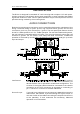
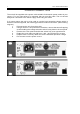
4 DL241 OPERATORS’ MANUAL POWER CONNECTION The unit will be supplied with a power cable suitable for domestic power outlets in your country. For your own safety it is important that you use this cable. The unit should always be connected to the mains supply earth using this cable If for some reason the unit is to be used at a mains input operating voltage which is different to that as supplied, the following procedure must be carried out. (see following diagram) 1: Disconnect the unit from the mains.
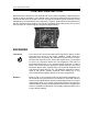
DL241 OPERATORS’ MANUAL 5 CONTROL DESCRIPTION Both channels of the DL241 are identical and may be used completely independently or linked for stereo operation. In the linked mode, only the left hand channel controls are functional and serve as master controls, though the channel bypass switches remain independent.
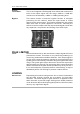
6 DL241 OPERATORS’ MANUAL COMPRESSOR Threshold: Determines the input level above which gain reduction will be applied and may be set in the range -40 to +20dB. Soft knee compression takes place for signals exceeding the threshold level by up to 10dB above which level, conventional 'ratio' compression is applied. Ratio: Sets the final compression ratio that will be applied once the 10dB 'soft-knee' region is exceeded. The ratio may be continuously adjusted from 1.
DL241 OPERATORS’ MANUAL Output Level Meter: Bypass: 7 This is an 8 segment LED bargraph level meter that monitors the level of the output signal over the range -20dB to +15dB with reference to the selected (-10dBu or +4dBu) operating level. This switch causes a 'hard-wire' bypass function of all signal processing for this channel, where the input socket is routed directly to the output socket. This feature enables the unit to pass audio even with no power applied to the DL241.
8 DL241 OPERATORS’ MANUAL OPERATION The unit should be connected in line with the signal to be processed via suitable insert points. Ensure that the insert send and return level on your console matches the operating level set up using the rear panel push-buttons on the DL241. If not, select the appropriate operating level on the DL241. For single channel use, each channel may be considered as being completely independent and set up accordingly.
DL241 OPERATORS’ MANUAL 9 The solution is either to use less compression or increase the attack time to allow the leading edge of the brighter sounds to pass through the compressor before the gain reduction occurs. In extreme cases, it may be necessary to add a little artificial brightness to the processed sound using equalisation or some form of exciter, though the semi-soft-knee compression system used in DL241 tends to minimise this side effect.
10 DL241 OPERATORS’ MANUAL IF A FAULT DEVELOPS For warranty service please call Drawmer Electronics Ltd. Or their nearest authorised service facility, giving full details of the difficulty. On receipt of this information, service or shipping instructions will be forwarded to you. No equipment should be returned under the warranty without prior consent from Drawmer or their authorised representative. For service claims under the warranty agreement a service Returns Authorisation (RA) number will be given.
DL241 OPERATORS’ MANUAL 11 TECHNICAL SPECIFICATIONS (Measurements taken at +4dBu operating level where applicable) INPUT IMPEDANCE 20KÙ MAXIMUM INPUT LEVEL +20dBu OUTPUT IMPEDANCE 50 Ù (bal), 100 Ù (unbal) MAXIMUM OUTPUT LEVEL +20dBu BANDWIDTH <10Hz to 22KHz -1dB NOISE AT UNITY GAIN with Expander Off Wideband 22Hz - 22KHz CCIR ARM IEC A Q-Pk CCIR AV -90dB -95dB -95dB -97dB -84dB RMS -88dB -93dB -93dB -95dB -82dB DISTORTION 100Hz 1KHz 10KHz Unity Gain, +4dBu input < 0.
12 DL241 OPERATORS’ MANUAL BLOCK DIAGRAM