
Owner's manual


DL241 OPERATORS’ MANUAL 3
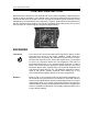
INSTALLATION
The DL241 is designed for standard 19" rack mounting and occupies 1U of rack space.
Avoid mounting the unit directly above power amplifiers or power supplies that radiate
significant amounts of heat. Fibre or plastic washers may be used to prevent the front
panel becoming marked by the mounting bolts.
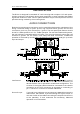
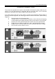
AUDIO CONNECTIONS
Both the input and output connectors may be used either balanced or unbalanced, the
wiring convention being for jacks: tip hot, ring cold and sleeve ground; and for XLR
connectors: pin 2 hot, pin 3 cold and pin 1 ground. The rear panel push buttons should
be out for +4dBu operation or in for -10dBu operation. For use with unbalanced systems,
the unit is directly compatible with mono jacks. The mono jack actually shorts the cold
terminal to ground. For the DL241 units fitted with XLR connectors, unbalanced
operation is achieved by shorting pin 3 of the XLR connector to ground (pin 1) at both
input and output.
Interference: If the unit is to be used where it maybe exposed to high levels of
disturbance such as found close to a TV or radio transmitter, we
advise that the unit is operated in a balanced configuration. The
screens of the signal cables should be connected to the chassis
connection on the XLR connector as opposed to connecting to
pin1. The DL241 conforms to the EMC standards.
Ground Loops: If ground loop problems are encountered, never disconnect the
mains earth, but instead, try disconnecting the signal screen on
one end of each of the cables connecting the outputs of the DL241
to the patchbay. If such measures are necessary, balanced
operation is recommended.