
Owner's manual


DL241 OPERATORS’ MANUAL 7
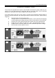
Output
Level Meter: This is an 8 segment LED bargraph level meter that monitors the
level of the output signal over the range -20dB to +15dB with
reference to the selected (-10dBu or +4dBu) operating level.
Bypass: This switch causes a 'hard-wire' bypass function of all signal
processing for this channel, where the input socket is routed
directly to the output socket. This feature enables the unit to pass
audio even with no power applied to the DL241. Normally the
switch is used to compare the raw unprocessed signal verses with
any expansion, compression and limiting of the audio input.
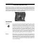
PEAK LIMITER
Level: Sets an absolute limit to the level that the output signal will not be
permitted to exceed. This limiter is very fast acting enabling it to
control any peaks without audible distortion. If the output signal is
so high as to cause the limiter to operate for more than 20mS, the
system gain is automatically reduced to bring the signal back within
range. The system gain is then returned to normal over a period of
approximately one second. The compressor Gain control should be
used to ensure that the peak limiter operates only rarely if at all, if
it is to be used purely for peak protection. Alternatively, it may be
deliberately driven into limiting to produce creative effects.
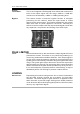
LINKING
Stereo Link: Depressing this switch configures the unit in stereo mode where
the left hand channel controls act as masters for both audio
channels. The same degree of gain reduction is applied to both
audio channels to prevent image shifting which would otherwise
occur whenever the left and right signal dynamics varied from each
other by any significant degree.