
Manual


6
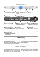
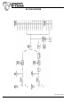
SIMPLE CONNECTION GUIDE
CHAPTER 2
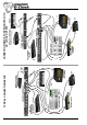
AES11
Is via an XLR connector designed to be used with standard
balanced microphone cable (20 metres maximum), wired
pin 1 screen, pin 2 and 3 balanced data, and the XLR shell
connected to the chassis. Having many short cables joined
together is not advisable as each connector can cause
undesirable signal reflections.
The output socket fully conforms to the EMC standards; if
the unit is to be used where it may be exposed to high
levels of disturbance, such as found close to a TV or radio
transmitter, it is suggested that the screen of the data cable
be connected to the chassis connection on the XLR type
connector rather than to pin 1.
If ground loop problems are encountered, never disconnect
the mains ground, but instead, try disconnecting the signal
screen on one end of each cable connecting the outputs.
Word Clock
Use only good quality 750 digital or video coax (not aerial
downlead) cable for the word-clock signals, terminated with
the correct type of 75Ω BNC connectors - inferior cables
will introduce jitter and will completely undermine the
performance benefits which might be achieved by using a
master clock in the first place!
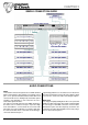
AUDIO CONNECTIONS