
Use and Care Manual


-9-
Assembly
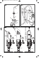
Identify the loose parts in the package based
on Fig. 1 and the list below
1 - Tube assembly
2 - Hanger wire
3 - Cord holder
4 - Crow’s nest
5 - Clamp wrench
6 - Base hex bolt and nut
7 - Height adjustment lever with square nut
8 - Base
9 - Drill press assembly
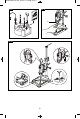
- Flip the base 8 upside down. Attach the hex
bolt 6B and nut 6A to the base as shown
(Fig. 2). Do not tighten just yet.
- Grab the drill press assembly 9. Loosen the
large angle lock knob 11 and small lock
knob 10. Rotate the angle adjustment
assembly 9A ninety degrees clockwise (Fig.
3).
- Using index finger, insert the square nut 7B
inside the drill press assembly 9 and screw
in the height adjustment lever 7 as shown
(Fig. 4). Do not tighten just yet.
- Pull plastic caps off of the tube assembly 1.
The easiest way to it is by “scraping” the
caps off using wrench 5 (Fig. 5). Once the
caps are off, avoid shaking the tube
assembly as the extension tube might slide
out.
- Pull the extension tube 1B about 2 - 3
inches through the top end (with plastic ring
1C). Lock the extension tube in place by
rotating the tubes in opposite directions as
shown (Fig. 5). This will prevent the
extension tube from sliding out.
- Slide the tube assembly into the drill press 9
as shown (Fig. 6). Make sure the plastic ring
1C of the tube assembly and the drill press
lever 12 are both pointing UP.
- Secure the drill press assembly 9 on the
outer tube 1 by tightening (clockwise) the
height adjustment lever 7 (Fig. 6).
- Insert the bottom end of the tube assembly
1 (without plastic ring 1C) into the base
column 8A and secure it in place by
tightening the base bolt 6 with 17mm
wrench or an adjustable wrench (not
included). See Fig. 7.
- With small holes pointing up, install the
crow’s nest 4 on the top end (with plastic
ring 1C) of the outer tube 1A (Fig. 9).
- Insert the cord holder 3 into the extension
tube 1B (Fig. 9).
- Insert the hanger wire 2 into the cord holder
3. Make sure the rubber cap is on the longer
end tip of the hanger wire (Fig. 9).
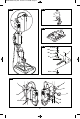
Mounting on workbench
Base 8 has to be securely mounted to
workbench.
Permanent attachment to workbench
using wood screws
All four mounting holes on the base should be
secured to workbench using 5/16" countersunk
wood screws (not included). See Fig. 8 a.
- Locate and mark where the base is to be
mounted.
- Drill four pilot holes in workbench.
- Place the base on the workbench, aligning
holes in base with pilot holes drilled in
workbench.
- Drive four screws to secure the base.
Permanent attachment to workbench
using bolts
All four mounting holes should be bolted
securely using 5/16" bolts, lock washers and
hex nuts (not included). See Fig. 8 b.
- Locate and mark where the base is to be
mounted.
- Drill four 5/16" diameter holes through work-
bench.
- Place the base on the workbench, aligning
holes in base with holes drilled in
workbench. Install bolts, lock washers and
hex nuts.
Temporary Mounting Using Clamps
“C” clamps (not included) can be used to
temporary mount the base to a workbench or
For illustrations refer to pages 2 - 6
Disconnect the plug from the power source and/or the battery pack
from the power tool before making any adjustments, changing
accessories, or storing power tools. Such preventive safety measures reduce the risk of
starting the power tool accidentally.
DM 2610921728_220 4/12/16 11:16 AM Page 9