Owner’s manual E 1
E 2
Hearty welcome among Ducati fans! Please accept out best compliments for choosing a Ducati motorcycle. We think you will ride your Ducati motorcycle for long journeys as well as short daily trips. Ducati Motor s.p.a wishes you smooth and enjoyable riding. We are steadily doing are best to improve our “Technical Assistance” service. For this reason, we recommend you to strictly follow the indications given in this manual, especially for motorcycle running-in.
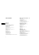
TABLE OF CONTENTS E General 6 Warranty 6 Symbols 6 Useful information for safe riding 7 Carrying the max load allowed 8 Identification data 9 Controls 10 Position of motorcycle controls 10 Instrument panel 11 Keys 12 Ignition switch and steering lock 12 Left switch 13 Clutch lever 14 Cold start lever 15 Right switch 16 Throttle twistgrip 16 Front brake lever 16 Rear brake pedal 17 Gear change pedal 17 Setting the gear change and rear brake pedals 18 4 Main components and devices 19 Location 19 Tank fill
Charging the battery 45 Chain tensioning 46 Chain lubrication 47 Replacing bulbs 47 Headlamp alignment 50 Tyres 51 Checking engine oil level 53 Cleaning and replacing the spark plugs 64 Cleaning the motorcycle 55 Storing the bike away 56 Important notes 56 Technical data 57 Overall dimensions 57 Weights 57 Top-ups 58 Engine 59 Timing system 59 Performance data 60 Spark plugs 60 Brakes 61 Transmission 62 Frame 63 Wheels 63 Tyres 63 Suspensions 63 Electric system 64 Monster versions 69 600/750/900 69 Dark 69
GENERAL E Warranty In your own interest, and in order to guarantee product reliability, you are strongly advised to refer to our authorized Dealers and workshops for any servicing requiring particular technical expertise. Our highly skilled staff have access to the implements required to perform any servicing job at best, and use Ducati original spare parts only as the best guarantee for full interchangeability, smooth running and long life. All Ducati motorcycles come with a “Warranty Card”.
Useful information for safe riding Warning Read this section before riding your motorcycle. Accidents are frequently due to inexperience. Always make sure you have your licence with you when riding; you need a valid licence to be entitled to ride your motorcycle. Do not lend your motorcycle to inexperienced riders or who do not hold a valid licence. Both rider and pillion passenger must always wear a safety helmet.
Carrying the maximum load allowed Your motorcycle is designed for long-distance riding, carrying the maximum load allowed in full safety. Even weight distribution is critical to preserving these safety features and avoiding trouble when performing sudden manoeuvres or riding on bumpy roads. E Information about carrying capacity The total weight of the motorcycle in running order including rider, pillion passenger, luggage and additional accessories should not exceed 370 Kg/816 lb.
Identification data All Ducati motorcycles have two identification numbers, for frame (fig. 1.1) and engine (fig. 1.2). 600/750 Frame number Engine number Note These numbers identify the motorcycle model and should always be indicated when ordering spare parts. E fig. 1.2 900 fig. 1.1 fig. 1.
CONTROLS 1 4 8 7 E Warning This section details the position and function of all the controls you need to drive your motorcycle. Be sure to read this information carefully before you use the controls. 3 6 5 2 Position of motorcycle controls (fig. 2) 1) Instrument panel. 2) Key-operated ignition switch and steering lock. 3) Left switch. 4) Clutch lever. 5) Fast-idle lever. 6) Right switch. 7) Throttle twistgrip. 8) Front brake lever. 9) Gear change pedal. 10) Rear brake pedal. 9 10 fig.
Instrument panel (fig. 3) 1) Speedometer (km/h or mph). Gives road speed. a) Odometer (km or miles). Gives total distance covered. b) Trip meter (km or miles). Gives distance covered since last resetting. c) Trip meter resetting knob. Turn to reset trip meter to “0000”. 2) Green light N. Comes on when gearbox is in neutral. 3) Yellow light . Comes on when there are about 3.5 liters/0.8 U.S.Gallons fuel left in the tank. 4) Green light . Comes on and flashes when a turn indicator is on. 5) Red light .
Keys (fig. 4) Your Ducati was delivered with two universal keys for ignition, steering lock and seat catch and a key identification plate (1). Note Separate the two keys and keep the identification plate in a safe place . Ignition switch and steering lock (fig. 5) It is located in front of the fuel tank and has four positions: A) ON: lights and engine on; B) OFF: lights and engine off; C) LOCK: steering lock; D) P: parking lights and steering lock.
Left switch (fig. 6) 1) Switch, light switch, 3 positions: Down = light off; Centre = front and rear parking light, number plate light and panel lights on; Up = headlamp, front and rear parking light, number plate light and panel lights on. Note This device is not fitted on the Australia and Japan versions. 2) Dip switch, light dip switch, two positions: position = low beam on; position = high beam on. E fig.
E Clutch lever (fig. 7) Lever (1) disengages the clutch. It features a dial adjuster (2) for lever distance from the twistgrip on handlebar. To set lever distance from twistgrip, push lever (1) fully forward and turn the dial adjuster (2) to one of its four positions. Remember that position no. 1 gives maximum distance between lever and twistgrip, whereas lever and twistgrip are closest when adjuster is set to position no. 4.
Cold start lever (fig. 8) Use this device to start the engine from cold. It will increase the engine idling speed after starting. Lever positions: A) (vertical) = closed B) fully open. Right switch (fig. 9) 1) Switch for ENGINE STOP, two positions: position (RUN) = run. position (OFF) = stop. The lever can be opened and closed gradually to adjust speed until engine is fully warm (see page 30). Important Never use the cold start lever when the engine is warm or leave it open when riding.
Throttle twistgrip (fig. 9) The twistgrip (3) on the right handlebar opens carburettor shutter (600/750) or the throttles (900). When released, it will spring back to the initial position (idling speed). E fig. 9 Front brake lever (fig. 9) Pull in the lever (4) towards the twistgrip to operate the front brake. The system is hydraulically operated and you just need to pull the lever gently.
Rear brake pedal (fig. 10) Push down on the pedal (1) to apply the rear brake. The system is hydraulically operated. Gear change pedal (fig. 11.1) The gear change pedal is at rest when in the central position N, is moved up and down to change gears and then returns to the central position. down = push down on the pedal to engage 1st gear and to shift down. The N light will go out. up = lift the pedal to engage the 2nd gear and then the 3rd, 4th, 5th and 6th gear (6th gear: 900 only).
Setting the gear change and rear brake pedals (fig. 11.2) The gear change and rear brake pedals can be adjusted to suit the preferred riding position of each rider. To set the gear change pedal, lock linkage (1) and loosen the check nuts (2) and (3). Note Nut (2) has a left-hand thread. E Rotate linkage (1) until setting pedal in the desired position. Tighten both check nuts onto linkage. To set the rear brake pedal, loosen check nut (4).
MAIN COMPONENTS AND DEVICES Location (fig. 12) 1) Tank filler plug. 2) Seat catch. 3) Hook for helmet fastening cable. 4) Passenger grab handle. 5) Side stand. 6) Rear view mirrors. 7) Shock absorber adjusters. 8) Shock absorber adjusters (900S). 9) Front fork adjusters (900S). 10) Fuel tank lifting rod. 11) Seat cover (DARK/CITYDARK excluded). 12) Fuel tank clip. E fig.
Tank filler plug (fig. 13) Opening Lift the protection lid (1) and fit the ignition key into the lock. Turn the key clockwise 1/4 turn to unlock. Lift the plug. E Closing Refit the plug with the key in it and push it down into its seat. Turn the key anticlockwise to its initial position and take it out. Close the lock protection lid (1). Note The plug can only be closed with the key in. In turn, the key can only be taken out after the plug has been closed.
Seat catch and helmet pin Opening Fit the ignition key into the lock. Turn the key clockwise to detach seat from frame. Pull the seat backwards to slide it off its front holders. On the rear end of the compartment underneath the seat, there is the helmet fastening cable (1) (see page 35). Insert the cable into the helmet, slide the end of the cable onto the pin (2). Leave helmet hanging outside and refit the seat. Warning This system is intended to lock your helmet safely when you park your motorcycle.
Side stand (fig. 15) Important Before lowering the side stand, make sure that the bearing surface is hard and flat. E Warning The motorcycle can be started only if the side stand is in “rest” position as it is equipped with a safety device preventing engine start if the stand is down. Do not park on soft or pebbled ground or on asphalt melt by the sun heat and similar or the motorcycle may fall over. When parking in downhill road tracts, always park the motorcycle with its rear wheel facing downhill.
Shock absorber adjusters (fig. 16) The shock absorber has outer adjusters that enable you to adjust your motorcycle to the load. The adjuster (1) located on the right side, on the connection holding the shock absorber to the swingarm, controls rebound damping. Turn the adjuster (1) clockwise to increase damping (H), anticlockwise to reduce it (S). STANDARD setting: turn the adjuster (1) all the way in (clockwise) then slacken it 8 clicks.
900S E Shock absorber adjusters The shock absorber has outer adjusters that enable you to adjust your motorcycle to the load. The adjuster (1, fig. 17.2) located at bottom, on the connection holding the shock absorber to the swingarm, controls rebound damping. The adjuster (2, fig. 17.1) on the left of the shock absorber expansion reservoir controls compression damping. Turn the adjusters (1 and 2) clockwise to increase damping, anticlockwise to reduce it.
Front fork adjusters The front fork of 900S models has rebound and compression damping adjusters. This adjustment is done using the outer adjusters: 1) (fig. 18.1) to adjust rebound damping; 2) (fig. 18.1) to adjust spring preload; 3) (fig. 18.2) to adjust compression damping. 3 Standard factory setting is as follows: compression: 5 clicks; rebound: 7 clicks. The max. setting range is 14 clicks (rebound) and 16 clicks (compression) that ensure the softest damping. 1 fig. 17.
To change the preload of the spring inside each fork leg, turn the adjusting nut (2) with a 22-mm/0.87-in. hexagon wrench. Preload setting range (A) is from 25 to 10 mm/0.99 to 0.39 in. Factory setting is 18 mm/0.7 in. 1 2 Important Adjust both fork legs to same settings. A 900S E fig. 18.1 3 fig. 18.
DIRECTIONS FOR USE Running-in recommendations This will enable a correct break-in of friction material on brake pads against brake discs. For all mechanical parts of the motorcycle to adapt to one another and above all not to adversely affect the life of basic engine parts, it is advisable to avoid harsh accelerations and not to run the engine at high rpm for too long, especially uphill. Furthermore, the drive chain should be inspected frequently. Lubricate it as required. Max.
After 2500 km/1553 miles After running-in, never exceed the following values during the motorcycle standard use: 600/750 models – max. speed allowed for each gear (see page 60). 900 models – 9000 rpm. E Strict observance of running-in recommendations will ensure longer engine life and reduce the likelihood of overhauls and tune-ups. fig. 19.2 900 fig. 19.1 28 fig.
Pre-ride checks Warning Failure to carry out these checks before riding, may lead to motorcycle damage and injury to rider and passenger. Warning In case of malfunctioning, do not start the motorcycle and call a Ducati dealer or authorized workshop. Before riding, perform a thorough check-up on your bike as follows: Fuel level in the tank Check fuel level in the tank. Fill tank if needed (page 33). Engine oil level Check oil level in the sump through the sight glass.
Starting the engine Note Follow the “High ambient temperature” procedure to start the engine when it is warm. E Warning Before starting the engine, become familiar with the controls you will need to use when riding. Never start or run the engine indoors. Exhaust gases are poisonous and may lead to loss of consciousness or even death within a short time. Regular ambient temperature (10 to 35 °C/50 to 95 °F): 1) Move the ignition key to ON (fig. 21.1).
High ambient temperature (over 35 °C/95 °F): Follow the same procedure, however, do not use the fast-idle device. Cold ambient temperature (below 10 °C/50 °F): Follow the procedure for “Regular ambient temperature”, however allow 5 minutes for the engine to warm up (step 5). 600/750 models have an automatic electric heating for float chambers. E fig. 21.2 fig. 21.1 fig. 21.
E Moving off 1) Disengage the clutch squeezing the control lever. 2) Push down on gear change lever sharply with the tip of your foot to engage the first gear. 3) Speed up engine, by turning the throttle twistgrip and slightly releasing the clutch lever at the same time. The motorcycle will start moving off. 4) Let go of clutch lever and speed up. 5) To shift to second gear, close the throttle to slow down engine, disengage the clutch right away, lift the gear change lever and let go of clutch lever.
Stopping the motorcycle Slow down gradually, then shift down and release the throttle twistgrip. Finally change from first to neutral. Apply brakes and you will bring the motorcycle to a complete stop. To switch the engine off, simply turn the key to OFF (fig. 22). Refueling Never overfill the tank when refueling. Fuel should never be touching the rim of filler recess (fig. 23). Warning Be sure there is no fuel trapped in the filler recess.
E Parking Stop the motorcycle, then put it on the side stand to park it (see page 22). To avoid theft, turn the handlebar fully left and turn the key to LOCK position. If you park in a garage or other facilities, make sure that there is proper ventilation and that the motorcycle is not near a source of heat or sparks. If nedeed, you may leave the parking lights on by turning the key to position P (fig. 24). Important Do not leave the key turned to P for long periods or the battery will run down.
MAINTENANCE Tool kit and accessories (fig. 25.1) The compartment under the seat holds: an Owner’s manual; a helmet fastening cable; a tool bag for normal maintenance and checks to be performed by the user. 1 E 2 fig. 25.1 To reach this compartment, remove the seat first (page 21) then the protective cover (1). Use a coin to unscrew its special screw (2). The tool bag holds (fig. 25.2) 3) box wrench for spark plugs; 4) tommy bar; 5) double-bit screwdriver; 6) helmet fastening cable. fig. 25.
E Routine maintenance The maintenance schedule below specifies maintenance operations to be carried out at regular intervals according to time (months) or distance covered (km or miles). It also shows the motorcycle parts requiring special care. Proper maintenance, as specified in the maintenance schedule, ensures long life to your motorcycle, top performance, good reliability and safe riding.
Operations Predelivery After 1000 km/ 621 miles or 6 months Every 1000 km/ 621 miles Every Every 10000 km/ 20000 km/ 6,214 miles 12,427 miles Spark plugs C S Carburettor: synchronization and idling adjustment (600/750) ( ■) C C Chain: tensioning and lubrication ( ■) C/ L Timing belts ( ■) C/ L C/ L C C C General testing C C Flexible cables C C C Clutch and brake hydraulic controls ( ■) C C C Cylinder compression ( ■) C Throttle body: synchronization and idling adjustment (900)
Operations Predelivery Engine oil filter ( ■) E After 1000 km/ 621 miles or 6 months Every 1000 km/ 621 miles S Every Every 10000 km/ 20000 km/ 6,214 miles 12,427 miles S Valve clearance ( ■) C Rear wheel rubber cush drive damper ( ■) C Signaling and light system V Battery liquid level C General lubrication ( ■) L L Clutch and brake control oil ( ■) C C C L C S Front fork oil ( ■) Engine oil ( ■) S C Wear on brake pads ( ■) S C C C Sprocket stop plate ( ■) C Tyres: wear and
MAIN MAINTENANCE OPERATIONS Lifting the fuel tank (fig. 26.1) E Warning Make sure the fuel in the tank is less than 5 litres/1.3 US.Gal. or fuel may leak out through the filler plug breather. fig. 26.1 Remove the seat (page 21) and lift the hook (1). Lift the tank and unhook the service rod (2, fig. 26.2) from the support. Place the tank onto the rod. When you have finished, reverse the above procedure to refit. Warning When lowering the tank, make sure lines are properly routed to avoid squeezing. fig.
Changing air filter (fig. 27.1) Replace the air filter at the required intervals shown in the routine maintenance chart. The air box is accessible after lifting the fuel tank as described on page 39. To remove the filter, release the cover clips (1) on both sides of the air box and take off the cover (2). Remove the filter cartridge (3, fig. 27.2) and fit a new one. E 2 Important A clogged filter will reduce air intake, increase fuel consumption, reduce engine power, and foul the spark plugs.
Checking brake and clutch fluid level (fig. 28) Fluid level should never fall below the MIN mark on each reservoir. If level drops below the limit, air might get into the circuit and affect the operation of the system involved. Brake and clutch fluid must be topped up and changed at the intervals specified in the routine maintenance chart by a Ducati dealer or authorized workshop. Important It is recommended all brake and clutch tubes be changed every four years.
Brake system If you find exceeding play on brake lever or pedal and brake pads are still in good condition, contact your Ducati dealer or an authorized workshop to have the system inspected and any air drained out of the circuit. E Warning Brake and clutch fluid and will damage paintwork and plastic parts if accidentally spilled. Hydraulic oil is corrosive; it may cause damages and lead to severe injuries. Never mix different quality oils. Check seals for proper sealing.
Lubricating cables and joints The condition of the outer sheaths of the throttle and fast-idle cables should be checked at regular intervals. The sheaths should show no signs of squeezing or cracking. Work the controls to make sure the cable slides smoothly inside the sheath: if you feel any friction or hard spots, have the cable replaced by your Ducati dealer or authorized workshop.
Throttle cable adjustment The throttle twistgrip must have a free play of 2 - 4 mm/0.08-0.16 in., measured at the edge of the twistgrip and at all positions of the handlebars. If it needs adjusting, use the suitable adjuster(s) (1, fig. 31) provided on the throttle control. E Checking battery liquid level (fig. 32) Lift the tank to carry out such operation (page 38). Battery liquid level must be maintained between the maximum (UPPER LEVEL) and minimum (LOWER LEVEL) marks on battery front.
Charging the battery (fig. 32) Before charging the battery, it is best to remove it from the motorcycle. Disconnect the breather tube (2). Always disconnect the black negative terminal (-) first, and then the red positive terminal (+). Release the retainers (3) and take the battery out of its mount. Refit the caps (1) on the cells and reinstall the battery on its mount and clamp the retainers (3). Reconnect the breather tube (2) and connect the terminals.
E Chain tensioning Turn the rear wheel slowly until you find the position where chain tension is highest. With the motorcycle on the side stand, push the chain up pressing with a finger at the point where it intersects with swing arm centerline. The lower portion of the chain should have a slack as follows (fig. 33.1): 20-25 mm/0.79-0.99 in. (600/750); 25-30 mm/0.99-1.18 in. (900). To adjust chain tension, slacken the nut (1, fig. 33.2) of the wheel spindle.
Chain lubrication The chain fitted on your motorcycle has OR seals that keep dirt out of and lubricant inside the sliding parts. The seals might be irreparably damaged if the chain is cleaned using non-specific solvents or washed using steam or water jets. Dry the chain using compressed air or absorbent material and apply SHELL Advance Chain or Advance Teflon Chain on each link. Important Using non-specific lubricants may lead to severe damage to chain, front and rear sprocket.
E Note Never touch the transparent body of the new bulb with your fingers or it will blacken resulting in reduced bulb brilliancy. Insert the locating pegs of the bulb base into their seats to obtain correct alignment; hook the clip (3) to the headlamp holders. Reconnect the cables. 600/750 instrument panel (fig. 35.1) Disassemble the instrument panel by unscrewing the two fastening screws (1) with washer (2). Disconnect the odometer cable (3) and the main wiring connector (4).
900 instrument panel (fig. 35.2) Disassemble the instrument panel by unscrewing the two fastening screws with washer. Disconnect the odometer cable (6) and the main wiring connector (7). Undo the four cap nuts (8) fastening the rear cover. Remove the instrument panel and the rear cover. Replace the burnt bulb with one with equal rating. Turn indicators (fig. 36) Remove the screw (1) and detach the glass (2) from the body. The bulb is of the bayonet-type: press and rotate anticlockwise to remove.
Stop light (fig. 37) To replace the stop and parking light bulb, unscrew the two screws (1) that secure the glass (2). Remove the glass. The bulb is of the bayonet-type: press and rotate anti-clockwise to remove. Fit the spare bulb by pressing and turning clockwise until it clicks. Refit the glass. E Number plate light (fig. 37) To expose the number plate bulb, withdraw the lamp holder from inside (3), then extract the bulb and replace it. Headlamp alignment (fig. 38.
Tyres Front pressure 2.1 bar - 2.3 Kg/sq cm (5.07 lb/sq cm) Rear pressure: 2.2 bar - 2.4 Kg/sq cm (5.29 lb/sq cm) As tyre pressure is affected by temperature and altitude variations, you are advised to check and adjust it whenever you are riding in areas where ample variations in temperature or altitude occur. E Important Check and set tyre pressure when tyres are cold. fig. 38.1 To avoid front wheel rim distortion, when riding on bumpy roads, increase front tyre pressure by 0.2 - 0.3 bar. fig. 38.
Tyre repair or replacement In the event of a tiny puncture, tubeless tyres will take a long time to deflate, as they tend to keep air inside. If you find low pressure on one tyre, check the tyre for punctures. E Warning A tyre must be replaced when punctured. Replace tyres using recommended standard tyres only. Be sure to tighten the valve caps securely to avoid leaks when riding. Never use tube type tyres.
Checking engine oil level (fig. 40) Engine oil level can be checked through the sight glass (1) provided on the clutch cover. When checking oil level, the motorcycle should be upright and the engine warm. Allow a few minutes for oil to settle to a steady level after stopping the engine. Oil level should be between the marks near the sight glass. Top up oil level with SHELL Advance Ultra 4, if low. Undo the filler plug (2) and top up to correct level. Refit the plug.
Important If the gap needs adjusting, be very careful when bending the side electrode. If gap is too wide or too close, engine performance will be affected. This could also cause difficult starting or irregular idling. Clean the electrode and the insulating material accurately using a small metal brush and check seal condition. Clean the seat in the cylinder head. Be careful not to let any foreign matters fall into the combustion chamber. Refit spark plug into cylinder head.
Cleaning the motorcycle To preserve the finish of metal parts and paintwork, wash and clean your motorcycle at regular intervals, anyway according to the road conditions you ride in. Use specific products only. Prefer biodegradable products. Avoid aggressive detergents or solvents. 900 Cromo tank Clean the tank with special (non-abrasive) products for chromium-plated surfaces at least once a month. This will keep your tank bright and shiny. Important Do not wash your motorcycle right after use.
E Storing the bike away If the motorcycle is to be left unridden over long periods, it is advisable to carry out the following operations before storing it away: clean the motorcycle; plug with its seal and empty the fuel tank; pour a few drops of engine oil into the cylinders through the spark plug seats, then crank the engine by hand a few times so a protective film of oil will spread on cylinder inner walls; place the motorcycle on the supplied service stand; disconnect and remove the battery.
TECHNICAL DATA Weights Dry weight: 174 Kg (600); 178 Kg (750); 185 Kg (900). 384 lb. (600); 392 lb. (750); 408 lb (900). Carrying full load: 318 Kg (600); 319 Kg (750); 331 Kg (900). 701 lb. (600); 703 lb. (750); 730 lb. (900). Overall dimensions (mm/in.) (fig. 42) Warning Failure to observe weight limits could result in poor handling and impair the performance of your motorcycle, and you may lose control of the motorcycle. 1030 / 40.55 (600/750) 1050 / 41.34 (900) 1130 / 44.49 (900S) 770 / 30.
Top-ups Type of fluid cu. dm. (liters)/ US Gall. Fuel tank, including a reserve of 3.5 cu dm (liters) / 0.92 US Gall. Gasoline 95-98 RON 16.5 Oil sump and oil filter SHELL Advance Ultra 4 3.1 / 0.82 (600) 3.3 / 0.87 (750) 3.9 / 1.03 (900) Front/Rear brake and clutch circuits SHELL-Advance Brake DOT 4 – Protectant for electric contacts SHELL-Advance Contact Cleaner – Front fork SHELL-Advance Fork 7.5 or Donax TA 0.440 / 0.
Engine Twin cylinder, four-stroke, 90° “L” type, longitudinal. Bore mm/in.: 80 (600); 88 (750); 92 (900). 3.15 (600); 3.46 (750); 3.62 (900). Stroke mm/in.: 58 (600); 61.5 (750); 68 (900). 2.28 (600); 2.42 (750); 2.68 (900). Total displacement cu.cm./cu. in.: 583 (600); 748 (750); 904 (900). 35.7 (600); 45.64 (750); 55.16 (900). Compression ratio ±0.5:1: 10.7 (600); 9.0 (750); 9.2 (900). Max. power at crankshaft (95/1/CE): 37,5 kW - 51HP at 8000 rpm (600). 45,6 kW - 62HP at 7500 rpm (750).
E Performance data Maximum speed in any gear should be reached only after a correct running-in period with the motorcycle properly serviced at the recommended intervals. Max. speed (rider alone): 175 Km/h/ - 109 mph (600); 165 km/h - 102 mph (for City 600 model); 190 Km/h - 118 mph (750); 180 km/h - 112 mph (for City 750 model); 210 Km/h - 130 mph (900); 200 km/h - 124 mph (for City 900 model). Speed limits for individual gears (600/750) (fig.
Brakes Front brake Type: drilled steel disc. 1 disc, left side (600/750 USA). 2 discs (750/900 USA version excluded). Disc diameter: 320 mm/12.6 in. Hydraulically operated by a control lever on right handlebar. Braking surface, sq cm/sq in.: 44 (600); 88 (750/900). 6.8 (600); 13.6 (750/900). Brake calipers with separate pistons. Make and type: BREMBO 30/34-4 pistons. Friction material: FERIT I/D 450 FF Master cylinder type: PS 13 (600); PS 16 (750); PSC 16 (900).
E Transmission Multiple-disk clutch in oil-bath (600/750); multiple-disk dry clutch (900); operated by a control lever on left handlebar. Drive is transmitted from engine to gearbox main shaft via spur gears. Ratio: 33/61 (600/750); 32/59 (900). Gearbox: 5-speed (600/750); 6-speed (900); with constant mesh gears, gear change pedal on left side of motorcycle. Front/rear sprocket ratio: 15/46 (600); 15/41 (750); 15/39 (900).
Frame Tubular trellis frame with upper section made of highstrength steel. Steering angle (on each side): 29° Steering head angle: 23° Trail mm/in.: 94/3.7 (600/750); 104/4.09 (900). Wheels Three-spoke, light-alloy rims. Front wheel Make: BREMBO Dimensions: 3.50x17" Rear wheel Make: BREMBO Dimensions: 4.50x17" (600/750); 5.50x17" (900). Both wheel spindles can be removed. Tyres Front tyre Tubeless, radial tyre. Size: 120/60-VR17 (600/750); 120/70-ZR17 (900). Rear tyre Tubeless, radial tyre.
E Electric system Basic electric items are: Round headlamp with iodine double filament bulb, 12V55/60W bulb. Parking light with 12V-5W bulb. Instrument panel, 12V-1.2W bulbs for warning lights and 12V-2W bulbs for instrument lights. Electric controls on handlebar. Turn indicators, 12V-10W bulbs. Warning horn. Stop light switches. Battery, 12V-16 A. Generator, 12V-520W. Electronic voltage regulator, protected by a 40 A fuse. Starter motor, 12V-0.7 kW.
600/750 1 2 E fig. 45.3 fig. 45.1 2 3 IN GOOD CONDITION 900 3 BLOWN fig. 45.2 fig. 45.
600/750 E Legend of the wiring diagram of electric system/ignition 1) Headlamp 2) Front right-turn indicator 3) Front left-turn indicator 4) Horn 5) Number plate light 6) Odometer 7) Instrument panel warning lights 8) Regulator 9) Key-operated switch 10) R.H. twistgrip switch 11) L.H.
32) Generator 33) Neutral light switch 34) Oil pressure sensor 35) Rear STOP light switch 36) Front STOP light switch 37) L.H. switch 38) Air temperature sensor 39) Instruments 40) Front, left-turn indicator 41) Headlamp 42) Front, right-turn indicator E Legend of fuse box (4) Pos. Description Rat. 1-9 Main switch 30 A 2-10 R.H. switch 7.5 A 3-11 High and low beams 15 A 4-12 Turn indicators, warning lights, tail lights and instrument panel lights 7.5 A 5-13 Stop, warning horn 7.
E Wire color coding P Pink GR-Bk Grey-Black Y-G Yellow-Green G Green R-G Red-Green W-R White-Red O-Bk Orange-Black V-Bk Violet-Black Y Yellow W-B White-Blue BN Brown G-W Green-White O-W Orange-White R-Bk Red-Black R-B Red-Blue GR-R Grey-Red R Red G-Bk Green-Black V Violet Y-Bk Yellow-Black GR Grey G-B Green-Blue Lb Light blue Bk Black Note Wiring diagrams for both systems are at the end of this 68
MONSTER VERSIONS 600/750/900 Available in the following colors: Ducati red 473.101; yellow 473.201; metallized grey 291.601; metallized black 291.500; metallized blue 291.800. Golden frame and wheel rims Dark This version differs from the basic version in the following features: - tank and front mudguard painted matt black; not varnished; - frame, arch and wheel rims come in black.
900Cromo This version differs from the basic version in the following features: - black frame and wheel rims; - chromium-plated fuel tank; - front and rear carbon mud guards; - carbon side panels; - carbon seat cowl; - rear anti-bounce kit.
Installing and setting the windscreen (fig. 46.1 and 46.2) Loosen the 2 screws (1) and the 4 screws (2). Slide the guides (3) onto the supports (4) gently. Do not force them. Line up the ends of supports (4) with the top ends of the guides (3). Set the windscreen (5, fig. 46.3) at the desired angle. Center the windscreen to the headlight and turn indicators. Tighten the screws (1) and (2). E 1 2 3 4 fig. 46.1 fig. 46.3 71 CITY CITYDARK fig. 46.
Side bags The side bags are designed to carry light baggage. Each bag carries 2 Kg/4.4 lb. maximum. Be sure to distribute the load evenly between the two side bags as well as inside each bag. CITY CITYDARK E Caution Carrying an exceeding load may impair handling and you may lose control of the motorcycle. Before moving off, always make sure the side bags are fixed securely to the motorcycle and secured in place with the key locks on the fastening supports properly closed.
Closing the bags (fig. 47.4) Strap the luggage in place inside the bag using the suitable straps. Close the zipper, lower the flap and lock the catch (2). Fit the key (1) and turn it one turn anticlockwise. The key can only be taken out of the lock when in this position. 3 4 E CITY CITYDARK 6 5 fig. 47.2 CLOSING 1 1 2 6 fig. 47.3 fig. 47.
Removing the bags (fig. 48.1) To take off the bag, fit the key (1) into the lock on the support. Turn the key 1/4 turn. Turn key anticlockwise in the LH fastening bracket lock, clockwise in the RH bracket lock. Take the key out of the lock. Rotate the top of the bag forward (in running direction) until releasing the upper catches from the studs (2, fig. 48.2). 1 CITY CITYDARK E 1 fig. 48.1 2 fig. 48.
Lift the bag off the bottom stud (3, fig. 48.3). For off-bike use, unbutton the two straps (4, fig. 48.4), fold out the rear flap and close the 270-degree zipper. 3 E 4 fig. 48.4 75 CITY CITYDARK fig. 48.
CITY CITYDARK E Installing the bags (fig. 49.3) Before fastening the bag to the motorcycle, be sure to remove the shoulder strap (5, fig. 47.2), if you have used it, and put it back into the inner compartment. Check that the rear flap is neatly folded and strapped down (4, fig. 48.4). Position the bag as shown in fig. 49.1, then push it down until you hear the bottom stud (3) click in place into the lower catch. Rotate the bag toward the tail of the motorcycle until hearing the two studs (2, fig. 49.
Bag maintenance and cleaning The bags are made from water-resistant materials that will keep water out effectively, but are not fully waterproof. This is why the bags come with waterproof storm covers for use in the event of heavy rain. Check the condition of locks and studs at regular intervals. Remove any dirt that may impair the full engagement of studs in their catches. Wash the bags with water and neutral soap only. Leave them to dry away from direct sunlight. 1 4 4 fig. 49.
Bag supports (fig. 50.1 and 50.2) Removal Remove the side bags. Unscrew the 4 screws (1) that hold the upper bracket of each bag to the frame. Remove the upper support of each bag from the frame. Loosen the two grub screws (2) from the inner face of each footpeg bracket and withdraw the bag bottom bracket from the footpeg bracket. CITY CITYDARK E Refitting Fit bottom bracket onto bag by sliding stud into lower catch.
Windproof cover (fig. 51) Removal Undo the two screws (1) securing the windproof cover to its supports. Remove the fork-type couplings from the rubber collars. Refitting Insert the fork-type couplings into the relevant rubber collars. Stand before your motorcycle and make sure that the windproof cover is centered with the headlamp (fig. 51). If not, adjust the windproof cover. Tighten the screws (1) and make sure the windproof cover is properly positioned. E 900S 1 fig.
E 80
Reporting of safety defects If you believe that your vehicle has a defect which could cause a crash or could cause injury or death, you should immediately inform the National Highway Traffic Safety Administration (NHTSA) in addition to notifying Ducati North America. If NHTSA receives similar complaints, it may open an investigation, and if it finds that a safety defect exists in a group of vehicles, it may order a recall and remedy campaign.
Noise and exhaust emission control system information USA E Source of Emissions The combustion process produces carbon monoxide and hydrocarbons. Control of hydrocarbons is very important because under certain conditions, they react to form photochemical smog when subjected to sunlight. Carbon monoxide does not react in the same way, but is toxic. Ducati utilizes lean carburetor settings and other systems to reduce carbon monoxide and hydrocarbons.
Riding safety The points given below are applicable for every day motorcycle use and shoud be carefully observed for safe and effective vehicle operation. A motorcycle does not provide the impact protection of an automobile, so defensive riding in addition to wearing protective apparel is extremely important. Do not let protective apparel give you a false sense of security. Before changing lanes, look over your shoulder to make sure the way is clear.
USA E When the roadway is wet, rely more on the throttle to control vehicle speed and less on the front and rear brakes. The throttle should also be used judiciously to avoid skidding the rear wheel from too rapid acceleration or deceleration. On rough roads, exercise caution, slow down, and grip the fuel tank with your knees for better stability. When quick acceleration is necessary as in passing, shift to a lower gear to obtain the necessary power. Do not down shift at too high an r.p.m.
Protective apparel Always wear a helmet. Most motorcycle accident fatalities are due to head injuries. For safety eye protection, gloves, and high top, sturdy boots should also be worn. The exhaust system becomes very hot during operation, never touch the exhaust system. Wear clothing that fully covers your legs. Do not wear loose clothing which could catch on the control levers, footrests, wheels, or chain.
Label location (fig. B) 12 1 10 2 8 7 3 11 4 5 6 USA E 9 fig.
USA E 87
California evaporation emission system This system consists of (fig. C and D): 1) Canister; 2) Fuel tank; 3) Induction manifold; 4) Carburettor; 5) Air intake manifold. 4 2 Important In the event of fuel system malfunction, contact Ducati’s authorized Service Centres. USA E 3 3 5 1 3 2 fig. C 4 3 1 5 fig.
I. Coverage Warranty defects shall be remedied during customary business hours at any authorized Ducati motorcycle dealer located within the United States of America in compliance with the Clean Air Act and applicable regulations of the United States Environmental Protection Agency and the California Air Resources Board. Any part or parts replaced under this warranty shall become the property of Ducati.
parts replaced and labor charges based on Ducati’s recommended time allowance for the warranty repair and the geographically appropriate hourly labor rate. The owner may be required to keep receipts and failed parts in order to receive compensation. USA E II. Limitations This Emission Control System Warranty shall not cover any of the following: A.
and durability may be used in the performance of any maintenance or repairs. However, Ducati is not liable for these parts. The owner is responsible for the performance of all required maintenance. Such maintenance may be performed at a service establishment or by any individual. The warranty period begins on the date the motorcycle is delivered to an ultimate purchaser. Ducati North America, Inc.. 237 West Parkway Pompton Plains, New Jersey, 07444-1028 001.973.
Routine maintenance record km/miles 1,000/621 10,000/6,214 E 20,000/12,427 30,000/18,641 40,000/24,855 50,000/31,068 92 Ducati Service Name Mileage Date
DUCATIMOTOR spa Via Cavalieri Ducati, 3 40132 Bologna, Italy Tel 39.051.6413111 Fax 39.051.406580 Internet: www.ducati.com 913.7.060.
600/750 G/Bk G/R Y OFF RUN R START W/R LOCK 30 34 86 OFF ON 87 85 D C 1 4 3 6 2 5 R 2 25 R/Y PARK B 30 9 10 3 11 4 12 5 13 6 14 7 15 8 16 33 R R/BK 40 Bn/Bk A B/Bk 17 R R/BK M R R O/B 31 32 YB16AL-A2 BN A YUASA R/B R/B BN O B A Y O/B W/G 10 W C 1 2 + Lb 10 – 9 R R/B W/Bn 4 W/G BK B/Bk 10 W 19 V/BK G 4 Gr/R 2 5 Y F 24 5/21 W 1 3 1 LO HI GND POS B C D A Y/BK W 5 5W Y W/G Y W/BK 3 W/BK BK W/BK 10 W W/G 1 B/Bk
OFF RUN START Lb W/R R 4 3 Y G/Bk G/R LOCK PARK OFF ON 85 R/B 1 9 10 11 12 13 14 15 16 1 2 3 4 5 6 7 8 R 86 87 4 3 2 6 5 30 49a Lb RB Bk P OB R R W/R BN 1 4 3 6 2 5 900 9 M 31 49+ 8 7 + 2 - 1 W/G BK W/R Y O R 4 2 5 Bn 42 W/G 10 W 10 10 W R/Bk 11 5/21 W 1 3 12 5W 41 LO HI GND POS BK W/BK 2 3 4 1 13 10 W 10 W R 20 A R 5 A R/B 14 - 40 + 28 W/Bk R/Bk 4 31 2 W/Bn 27 S K Bn/W Bk P/Bk B 87 A 30 Bk R W W/R B N F L H G 14 M 15