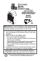
VENT-FREE GAS FIREPLACE INSERT OWNER’S OPERATION AND INSTALLATION MANUAL MODEL FDF150T PFS ® US WARNING: If the information in this manual is not followed exactly, a fire or explosion may result causing property damage, personal injury or loss of life. — Do not store or use gasoline or other flammable vapors and liquids in the vicinity of this or any other appliance. — WHAT TO DO IF YOU SMELL GAS • Do not try to light any appliance.
TABLE OF CONTENTS Safety......................................................... 3 Qualified Installing Agency......................... 4 Specifications............................................. 5 Product Features........................................ 5 Local Codes............................................... 5 Unpacking.................................................. 6 Product Identification.................................. 6 Water Vapor: A By-Product Of Unvented Room Heaters....................
SAFETY IMPORTANT: Read this owner’s manual carefully and completely before trying to assemble, operate, or service this heater. Improper use of this heater can cause serious injury or death from burns, fire, explosion, electrical shock and carbon monoxide poisoning. Failure to follow these instructions will void the warranty. Only a qualified installer, service agent, or local gas supplier may install and service this product.
SAFETY WARNING: You must operate this heater with screen in place. Any safety screen or guard removed for servicing an appliance must be replaced prior to operating the appliance. 1. Do not place propane supply tank(s) inside any structure. Propane supply tank(s) must be placed outdoors. 2. This heater shall not be installed in a bedroom or bathroom. 3. This heater needs fresh air ventilation to run properly. This heater has an Oxygen Depletion Sensing (ODS) safety shutoff system.
SPECIFICATIONS Model FDF150T Gas Type Natural Gas Propane Gas Maximum Input Rating 15,000 Btu/Hr 15,000 Btu/Hr Minimum Input Rating 7,000 Btu/Hr 11,000 Btu/Hr Pressure Regulator Setting 4" W.C. 9" W.C. Max. 10" Max. 14" Inlet Gas Pressure* (inches of water) Min. 5" Min. 11" Ignition Electronic Piezo Heater Dimensions (WxHxD) • 16" × 27.7" × 10.75" Carton Dimensions (WxHxD) • 18.9" × 30.79" × 13.25" Heater Weight • 38 lbs Shipping Weight • 41.3 lbs * For purposes of input adjustment.
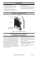
UNPACKING 1. 2. 3. 4. 5 6. Remove top inner pack. Tilt carton so that heater is upright. Remove protective side packaging. Slide heater out of carton. Remove protective plastic wrap. Hold the screen, lift, and pull forward. 7. Remove log set by cutting plastic ties. 8. Carefully unwrap log. 9. Check for any shipping damage. If heater or log is damaged, promptly inform your dealer where you bought the heater.
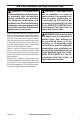
AIR FOR COMBUSTION AND VENTILATION WARNING: This heater shall not be installed in a confined space or unusually tight construction unless provisions are provided for adequate combustion and ventilation air. Read the following instructions to insure proper fresh air for this and other fuel-burning appliances in your home. Today’s homes are built more energy efficient than ever. New materials, increased insulation and new construction methods help reduce heat loss in homes.
AIR FOR COMBUSTION AND VENTILATION VENTILATION AIR Ventilation Air From Inside Building This fresh air would come from an adjoining unconfined space. When ventilating to an adjoining unconfined space, you must provide two permanent openings: one within 12" of the ceiling and one within 12" of the floor on the wall connecting the two spaces (see options 1 and 2, Figure 2). You can also remove door into adjoining room (see option 3, Figure 2). Follow the National Fuel Gas Code, ANSI Z223.
INSTALLATION NOTICE: This heater is intended for use as supplemental heat. Use this heater along with your primary heating system. Do not install this heater as your primary heat source. If you have a central heating system, you may run system’s circulating blower while using heater. This will help circulate the heat throughout the house. In the event of a power outage, you can use this heater as your primary heat source. WARNING: A qualified service person must install heater. Follow all local codes.
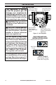
INSTALLATION GAS SELECTION This appliance is factory preset for propane gas. No changes are required for connecting to propane. Only a qualified installer or service technician can perform gas selection and connecting to gas supply. Insert Gas Fitting for Propane Gas Insert Gas Fitting for Natural Gas Blue Propane Gas Plunger Underneath Dust Cover Yellow Natural Gas Plunger Underneath Metal Cap CAUTION: Two gas line installations at the same time are prohibited.
INSTALLATION 2. Apply thread sealant to the threads on the connection fitting. While pushing in, rotate the fitting clockwise until the threads engage the regulator. After the fitting has been hand tightened into the regulator use a wrench to complete tightening of the fitting. Install additional fitting to connect to the house supply. Use only the cap supplied on the regulator. Do not use an off the shelf pipe plug. This can damage the plunger.
INSTALLATION BUILT-IN FIREPLACE INSTALLATION WARNING: Do not allow any combustible materials to overlap the firebox front. WARNING: Do not allow combustible or noncombustible materials to cover any necessary openings like louvered slots. 1/4" Clearance to Facia 3/8" Clearance to Sides, Back and Top 15 5/8" 16" WARNING: Never modify or cover the louvered slots on the front of the firebox.
19" 90° 25 3. Attach gas line to fireplace gas regulator. See Connecting to Gas Supply, page 14. 4. Check all gas connections for leaks. See Checking Gas Connections, page 16. IMPORTANT: When finishing your firebox, combustible materials such as wall board, gypsum board, sheet rock, drywall, plywood, etc, must have 1/2" clearance to the sides and top of the firebox. Combustible materials should never overlap the firebox front facing.
INSTALLATION CONNECTING TO GAS SUPPLY WARNING: A qualified service technician must connect heater to gas supply. Follow all local codes. CAUTION: Avoid damage to regulator. Hold gas regulator with wrench when connecting into gas piping and/or fittings. WARNING: This appliance requires a 3/8" NPT (National Pipe Thread) inlet connection to the pressure regulator. CAUTION: Use pipe joint sealant that is resistant to gas (Propane or Natural Gas).
INSTALLATION The installer must supply an external regula- Install sediment trap in supply line as shown tor. The external regulator will reduce incom- in Figure 11. Place sediment trap where it is ing gas pressure. You must reduce incoming within reach for cleaning. Place sediment trap gas pressure to between 11" and 14" of water. where trapped matter is not likely to freeze. If you do not reduce incoming gas pressure, A sediment trap traps moisture and contamiheater regulator damage could occur.
INSTALLATION CHECKING GAS CONNECTIONS WARNING: Test all gas piping and connections for leaks after installing or servicing. Correct all leaks at once. WARNING: Never use an open flame to check for a leak. Apply a noncorrosive leak detection fluid to all joints. If bubbles form, there is a leak. Correct all leaks at once. PRESSURE TESTING GAS SUPPLY PIPING SYSTEM Test Pressures In Excess Of 1/2 PSIG (3.5 kPa) 1.
INSTALLATION PRESSURE TESTING HEATER GAS CONNECTIONS 1. Open equipment shutoff valve (see Figure 17, page 16). Apply a noncorrosive leak 15, page 16). detection fluid to all joints. Bubbles forming show a leak. 2. Open main gas valve located on or near gas meter for natural gas or open propane 5. Correct all leaks at once. supply tank valve. 6. Light heater (see Lighting Instructions on 3. Make sure control knob of heater is in the page 19). Check all other internal joints OFF position. for leaks. 4.
INSTALLATION BATTERY INSTRUCTIONS CAUTION: Do not dispose of batteries in fire, batteries may explode or leak. • Battery is included. • Remove battery when depleted. • Be sure to observe proper polarity (+/-) when installing or replacing the battery. Damage due to improper battery installation may void the warranty on the product. • For long periods of non-operation, remove batteries from all components for safety. Unscrew ignitor cap and install a AAA battery with the + pointing out. Replace cap.
OPERATION LIGHTING INSTRUCTIONS WARNING: You must operate this heater with the screen in place. Make sure screen is installed before running heater. NOTICE: During initial operation of new heater, burning logs will give off a paper-burning smell. Orange flame will also be present. Open damper or window to vent smell. This will only last a few hours. 1. STOP! Read the safety information above. 2. Unscrew ignitor cap and install a AAA battery with the + pointing out. Replace cap. 3.
OPERATION THERMOSTAT CONTROL OPERATION The thermostatic control used on this model differs from standard thermostats. Standard thermostats simply turn the burner on and off. The thermostat used on this heater senses the room temperature. At times the room may exceed the set temperature. If so, the burner will shut off. The burner will cycle back on when room temperature drops below the set temperature. The control knob can be set to any comfort level between HIGH (5) and LOW (1).
INSPECTING BURNERS IMPORTANT: Owner’s should check pilot flame pattern and burner flame pattern often. Incorrect flame patterns indicate the need for cleaning (see Care and Maintenance, page 22) or service. WARNING: Only a qualified service person should service and repair heater. This includes maintenance requiring replacement or alteration of components. PILOT FLAME PATTERN Figure 24 shows a correct pilot flame pattern. Figure 25 shows an incorrect pilot flame pattern.
CARE AND MAINTENANCE WARNING: Turn off heater and let cool before servicing. CAUTION: You must keep control areas, burner, and circulating air passageways of heater clean. Inspect these areas of heater before each use. Have heater inspected yearly by a qualified service technician. Heater may need more frequent cleaning due to excessive lint from carpeting, bedding material, pet hair, etc. WARNING: Failure to keep the primary air opening(s) of the burner(s) clean may result in sooting and property damage.
CARE AND MAINTENANCE ODS/PILOT CAUTION: Never use a wire, needle, or similar object to clean ODS/pilot. This can damage ODS/ pilot unit. Natural Gas Burner Use a vacuum cleaner, pressurized air, or a small, soft bristled brush to clean. A yellow tip on the pilot flame indicates dust and dirt in the pilot assembly. There is a small pilot air inlet hole about 2" from where the pilot flame comes out of the pilot assembly (see Figure 29). With the unit off, lightly blow air through the air inlet hole.
TROUBLESHOOTING WARNING: If you smell gas: • Shut off gas supply. • Do not try to light any appliance. • Do not touch any electrical switch; do not use any phone in your building. • Immediately call your gas supplier from a neighbor’s phone. Follow the gas supplier’s instructions. • If you cannot reach your gas supplier, call the fire department. WARNING: Only a qualified service technician should service and repair heater. Make sure that power is turned off before proceeding.
TROUBLESHOOTING Problem Possible Cause Corrective Action When ignitor button is 1. Ignitor electrode is posi- 1. Replace electrode. pressed in, there is no tioned wrong. Ignitor elecspark at ODS/pilot trode is broken. 2. Ignitor electrode is not con- 2. Replace ignitor cable nected to ignitor cable. 3. Ignitor cable is pinched or 3. Free ignitor cable if pinched wet. by any metal or tubing. Keep ignitor cable dry. 4 Broken ignitor cable. 4. Replace ignitor cable. 5. Bad piezo ignitor. 5.
TROUBLESHOOTING Problem Possible Cause Corrective Action Burner(s) does not light 1. Burner orifice is clogged. after ODS/pilot is lit 1. Clean burner orifice (see Care and Maintenance, page 22) or replace burner orifice. 2. Burner orifice diameter is too 2. Replace burner orifice. small. 3. Inlet gas pressure is too low. 3. Contact local gas supplier. Delayed ignition of 1. Manifold pressure is too low. 1. Contact local gas supplier. burner(s). 2. Burner orifice is clogged. 2.
TROUBLESHOOTING Problem Possible Cause Corrective Action Heater produces a click- 1. Metal is expanding while 1. This is common with most ing/ticking noise just after heating or contracting while heaters. If noise is excesburner is lit or shut off. cooling. sive, contact qualified service technician. White powder residue 1. When heated, the vapors 1. Turn heater off when using forming within burner from furniture polish, wax, furniture polish, wax, carpet box or on adjacent walls carpet cleaners, etc.
PARTS MODEL FDF150T 1 2 4 3 5 14 10 13 6 9 12 11 8 15 7 18 19 16 28 17 www.factorybuysdirect.
PARTS MODEL FDF150T This list contains replaceable parts for your heater. When ordering replacement parts, follow the instructions listed under Replacement Parts on page 30 of this manual.
REPLACEMENT PARTS Note: Use only original replacement parts. This will protect your warranty coverage for parts replaced under warranty. PARTS UNDER WARRANTY Contact authorized dealers of this product. If they can’t supply original replacement parts, call Customer Service toll free at 1-855-607-6557 for referral information.
SERVICE HINTS When Gas Pressure Is Too Low • pilot will not stay lit • burners will have delayed ignition • fireplace will not produce specified heat • propane gas supply might be low (propane units only) You may feel your gas pressure is too low. If so, contact your local gas supplier. TECHNICAL SERVICE You may have further questions about installation, operation, or troubleshooting. If so, contact Factory Buys Direct at 1-855-607-6557.
WARRANTY KEEP THIS WARRANTY Model ________________________________ Serial No. _____________________________ Date Purchased ________________________ Keep receipt for warranty verification. REGISTER YOUR PRODUCT AT WWW.FACTORYBUYSDIRECT.