II OIL-FIRED CAST IRON HOT WATER BOILERS Installation Operation Repair Parts EPA Saving The Earth DOE Saving Your Money These instructions must be affixed on or adjacent to the boiler DUNKIRK BOILERS DUNKIRK, NEW YORK 14048 • AREA CODE 716 366-5500 MEMBER: The Hydronics Institute
INTRODUCTION The Empire Water boiler is a natural draft oil fired hot water boiler comprised of cast iron sections. The Empire Water boiler is available with 3, 4, or 5 cast iron sections. These sections are held together by cast iron push nipples. The Empire Water boiler is capable of firing #2 fuel oil from 0.65 gph up to 2.00 gph.
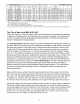
BOILER WITH TANKLESS MODEL NO. WITHOUT TANKLESS NO. SEC. INPUT *MBH **HEATING CAPACITY NET I=B=R RATING FIRING RATE A.F.U.E. MINIMUM CHIMNEY DIMENSIONS *MBH 70 80 +GPH 0.65 0.75 ++ 86.3 85.2 SIZE/HEIGHT 8" X 8" X I5" 8" X 8" X I5" COIL >>3EW.65T >>3EW.75T COIL >>3EW.65Z >>3EW.75Z 3 3 91 105 *MBH 80 92 3EW 1.00T >>4EW.90T 4EW1.25T 4EW1.50T 3EW 1.00Z >>4EW.90Z 4EW1.25Z 4EW1.50Z 3 4 4 4 140 126 175 210 II9 I11 I50 I78 I03 97 130 155 1.00 0.90 1.25 1.50 83.4 86.0 83.9 82.
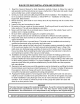
RULES FOR SAFE INSTALLATION 1. 2. 3. 4. 5. 6. 7. 8. 9. 10. 11. AND OPERATION Read the Owner's Manual for Safe Operation carefully. Failure to follow the rules for safe operation and the instructions can cause a malfunction of the boiler and result in death, serious bodily injury, and/or property damage. Check your local codes and utility requirements before installation.
BEFORE YOU START Complete all of the following prior to installing the boiler. A.Check to be sure you have selected the right size boiler with the proper capacity. The I=B=R rating of the boiler selected should be greater than or equal to the calculated peak heating load (heat loss) for the building or area(s) served by the boiler and associated hot water heating systems. See boiler rating and capacity table previously listed in this manual.
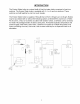
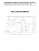
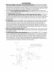
BURNER KEEP IS SHUT FORAN PERIOD OF TIME. I ALWAYS THEDOWN MANUAL FUELEXTENDED SUPPLY VALVE SHUT OFF, IF THE INSTALLATION ELECTRIC BVERCURRENT PROTECTED SAFETY SWITCH --- REQUIREMENTS LINE SERVICE FILL VALVE AND SHUTOFF DIAPHRAGM EXPANSION TANK ]}RAPT 2 _ FILL REGULAI PIPE --I NIN, 2" ID, VENT PIPE--, \ S @R _ VENT PIPE _'_L]NES_O J H --- RELIEF DUTS]DE RAD[ATIHN RAIJIATION CIRCULATING PUMP IN RETURN LINE OR AFTER THE EXPANSION TANK O_L TANK 1 / FDUN_ATIONS OIL J OIL LINES -x GENERA
FRESH AIR FOR COMBUSTION WARNING Be sure to provide enough fresh air for combustion. Enough air ensures proper combustion and assures that no hazard will develop due to the lack of oxygen. If you use a fireplace or a kitchen or a bathroom exhaust fan, you should install an outside air I intake. These devices will rob the boiler andNOTE water heater of combustion air. I You must provide enough fresh air to assure proper combustion. The fire in the boiler uses oxygen. It must have a continuous supply.
B= All Air from Outdoors: The confined space shall be provided with two permanent openings, one commencing within 12 inches of the top and commencing within 12 inches of the bottom of the enclosure. The openings shall communicate directly, or by ducts, with the outdoors or spaces (crawl or attic) that freely communicate with the outdoors. 1.
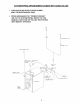
SYSTEM PIPING 1. When the installation of the boiler is for a new heatinq system, first install all of the radiation units (panels, radiators, baseboard, or tubing) and the supply and return mains. After all heating system piping and components have been installed, make final connection of the system piping to the boiler. It is recommended to mount the circulating pump on the supply side piping, such that it pumps away from the expansion tank. Refer to the figures on the next pages. 2.
SYSTEM PIPING ARRANGEMENT > CIRCULATOR ON SUPPLY PIPING AWAY FROM EXPANSION TANK ZONING WITH ZONE VALVES PUMPS PIPING ARRANGED FOR "POWER PURGING" AIR OUT OF SYSTEM PIPING, REFER TO THIS MANUAL'S SECTION ON "FILLING THE SYSTEM WITH WATER" OPTION #1 BALANCING ._ RETURN FROM VALVE ZONE VALVE \ S¥_TEN l SUPPLY SYSTEM TO CIRCULATOR PUNP SHUTOFF VALVE BOILER SERVICE-- FILLTROL WITH AIR PURGER FILL LINE WiTH SHUTOFF VALVE" ---AQUASTAT BOILER DRAIN VALVE_- SUPPLY SYSTEM VALVES TO
SYSTEM PIPING ARRANGEMENT - ZONING WITH CIRCULATORS > CIRCULATOR ON SUPPLY PIPING AWAY FROM EXPANSION TANK PUMPS > PIPING ARRANGED PURGING" FOR "POWER AIR OUT OF SYSTEM PIPING, REFER TO THIS MANUAL'S SECTION ON "FILLING THE SYSTEM WITH WATER" OPTION #1 / I VALVE BALANCING FLOW CHECK ZONE CIRCULATOR ISOLATION VALVE J I SUPPLY SYSTEM SHUTOFF BOILER VALVE SERVICE_ TO \ \\ AIR PURGER FILLTROL WITH FiLL LINE WITH SHUTOFF VALVE_ BOILER BRAIN 10 SUPPLY SYSTEM '\ / VALVE TO
SYSTEM PIPING ARRANGEMENTALTERNATE > DIAPHRAGM EXPANSION > CIRCULATOR ON SUPPLY PIPING PUMPS AWAY FROM EXPANSION > PER THIS MANUAL, TANK MOUNTED NEAR BOILER PIPING USE OPTION #2 IN "FILLING > THIS PIPING ARRANGEMENT CIRCULATORS RETURN PROM OFF THE BOILER THE SYSTEM TANK WITH WATER" CAN BE USED WITH ZONE VALVES OR ZONE SYSTEM SHUTOFF BOILER VALVE SERVICE ] / SUPPLY SYSTEM TO ISOLATION VALVES LINE WITH SHUTOFF VALVE BOILER DRAIN LOCATE CIRCULATOR PUHP HERE WHEN SYSTEM PIPING USES ZONE
, Boilers may be factory packaqed with a tankless heater coil see figure below. This coil provides instantaneous heating of water for domestic use - if proper burner and water supply line controls are used. Tankless coils are meant to provide domestic hot water for intermittent draws, not continuous flow. IMPORTANT Do not use a tankless coil if your water is excessively hard with lime or other deposits which will accumulate inside the coil.
. Antifreeze added to boilers must be non-toxic, and must be of a type specifically intended for use in closed hydronic heating systems. Under no circumstances should automotive antifreeze be used. Antifreeze used in any boiler may reduce capacity by 10% or more and increase fuel consumption. Tankless coil performance will fall as concentration of antifreeze is increased. Refer to boiler and piping water volumes tables in this manual.
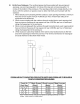
Foroil-firedboilersfor connectionsto ventsor chimneys,vent installationsshall be in accordancewith applicableprovisionsof INSTALLATIONOF OIL BURNINGEQUIPMENT, NFPA-31- latestrevision,andapplicableprovisionsof localbuildingcodes. CHIMNEYAND CHIMNEY CONNECTIONS This is a very important part of your heating system. No boiler, however efficient its design, can perform satisfactorily if the chimney that serves it is inadequate.
TYPICAL CHIMNEY CrINNECTIF1N BE REQUIRED MINIMUM HEIGHT, MUST BE AT LEAST 3 FT, HIGHER THAN HIGHEST PART OF PASSAGE THROUGH ROOF, MUST BE AT LEAST 2 FT, HIGHER THAN ANY NEIGHBORING OBJECT, MUST UNDI_STRUCTED MUST BE AT LEAST INCHES THICK AND BE HAVE TOP AN OPENING f 4 - MUST SLOPE UP AT LEAST i,/4 INCH PER FOOT OF HORIZONTAL RUN_ IN \ \ DRAFT VANE REGULATOR THIMBLE DRAVBAND LAST PIECE INSTALLED ALTERNATE POSITIONS TOP I 15
ELECTRICAL CONNECTIONS Thermostat Install a 24-volt thermostat (not provided) in a proper location. The location of the thermostat has an important effect on boiler system operation. BE SURE TO FOLLOW THE INSTRUCTIONS INCLUDED WITH THE THERMOSTAT. Groundinq Permanently ground the boiler according to local codes and the National Electrical Code. Run a 14 gauge or heavier copper wire from the boiler to a grounded connection in the service panel or a properly driven and electrically grounded ground rod.
EQUIPMENT AND OPTIONAL ACCESSORIES RELIEF VALVE (provided) Each low pressure hot water heating boiler is provided with a relief valve for over pressure protection of the boiler and heating system. The relief valve will open when the pressure in the boiler rises to 30 psig. Each relief valve is provided with a lifting device for testing and should be tested monthly during the heating season.
MAIN AIR VENT: for down flow systems or diaohraam orovided_ Before a system is filled with water, Some of the air will be trapped as the system air through the air vents on the radiation units. process. The main air vent should be installed all radiation is below the top of the boiler. AUTOMATIC tvoe exoansion tanks (not there is air in the pipes and radiation units. is filled.
FILLING THE BOILER HOW A HOT WATER SYSTEM OPERATES The entire heating system (boiler, piping, and radiation units) is filled with water. As the water in the boiler is heated, it is circulated from the top of the boiler through the supply main to the radiation units. The cooler water in the radiation units flows back through the return piping through the return main into the boiler. This arrangement provides positive and rapid response to the thermostat.
OPERATING I I DO NOT TAMPER THE BOILER WITH THE UNIT OR CONTROLS IMPORTANT - You or your installer must follow these instructions carefully. STARTING: Fill the entire system with water. Vent all air from the system following section for FILLING THE BOILER. the FUEL UNITS AND OIL LINES: Install oil line(s) to the oil burner. Recommend using heavy wall copper tubing and flared fittings, not compression fittings. All connections and joints must be absolutely airtight.
NOZZLES AND ELECTRODES: the recommended Use the proper size, spray angle, and spray pattern nozzle. Refer to nozzle selection nozzle line electrode assembly, charts at the end of this manual. To install a nozzle, remove the if necessary tighten the nozzle. Be careful not to damage After installing the nozzle, reassemble remove the retention the electrode ring assembly, insulators the nozzle line electrode and then install and or the bend the electrode assembly tips.
E[
_ 5/32 _' 4rqm / ( 5/64" -- --5/32" op _o 7/64" o1," 2"_m to £,Drqrq 4mm 13/64 or 5/32" 23 t,o 13/64" or" 4nn _ 5mm
CHECKING AND ADJUSTING CONTROLS A boiler using a tankless coil is configured with a Honeywell L8124C Combination Hi/Low Limit Aquastat Relay (refer back to the SYSTEM PIPING section for more details). A boiler not using a tankless coil is configured with a Honeywell L8148A Hi Limit Aquastat Relay. Instructions for the control provided are included with the boiler.
MAINTENANCE ANNUALLY: To assure trouble-free operation, it is recommended that the flue passages, combustion chamber area (target wall, fire door insulation, durablanket), burner adjustment, operation of the controls, and boiler seals (fire door gasket or silicone seal, cast iron sectional seals, flue collector) be checked once each year by a competent Service Technician.
OIL BOILER OIL BOILER / BURNER CLEANING INSTRUCTIONS CLEANING: 1. Shut off all electrical power to the boiler / burner and shut off fuel oil supply. 2. Remove the vent pipe from the top of the boiler. Inspect the pipe and chimney for signs of corrosion and deterioration. Clean out the base of the chimney. If the vent pipe shows any signs of corrosion or deterioration, replace it immediately. If chimney damage or deterioration is discovered, contact a competent professional. 3.
OIL BURNER CLEANING: These are aeneral instructions for cleanina an oil burner. For specifics. consult the burner manufacturer's instructions. 1. Make sure all electrical shut off. power to the boiler / burner and the fuel supply to the burner are 2. With the swing door open, clean any soot accumulations from the end of the burner and if applicable burner head. 3. Remove the burner drawer assembly, clean the electrodes and then reset the electrode spark gap per the manufacturer's recommendations.
SERVICE You may avoid inconvenience HINTS and service calls by checking these points before you call for service. Possible Cause What to do Thermostat is not set correctly Reset thermostat above room temperature. Boiler or Burner may be dirty Clean all flue passages and the vent pipe. Have burner cleaned and readjusted. Burner may not be firing at proper rate Check nozzle size if there is any doubt. Have burner adjusted.
ELECTRICAL WIRING BOILER WITH TANKLESS COILANDAND HONE_NELL L8124CAQUASTAT CONTROL BOILERWITHOUTTANKLESS COILANDAND HONE_NELL L8148AAQUASTAT CONTROL (BECKETTAFG (BECKETTAFG BURNER SHOWN) 24 VOLT TNERMOSTAT 12OV POWER SUPPLY BURNER SHOWN) 120V POWER SUPPLY 24 VOLT THER_OST_ II COL_CODE LS 1 €8A AQUASTAT / --Y£LLOW w -WH_ -£LUE V -_OLET LmEVOL_E i ......... .... @@ BN W IGN.
BOILER WITH TANKLESS COILAND BOILER WITHOUT TANKLESS COIL AND HONEYWELLL8124CAQUASTATCONTROL HONEYWELLL8148AAQUASTATCONTROL (CARLINEZ BURNER SHOWN) (CARLINEZ BURNER SHOWN) 24 VOLT THERMOSTAT 120V POWER _ NEUTRAL --_"_ _-,-,-,-,%ft BK W I I 120V P0WZR SUPPLY T_R_%AT I i I o v OP_N_E ygLt O_*r izo/_ol, ov[_u._,RE I PROTECTED DISCONNECT II _j BK w _ I i L8124C J AQUASTAT L8148A :'4 VOL_S ....
BOILER WITH TANKLESS COILAND BOILER WITHOUT TANKLESS COIL AND HONEYWELL L8124CAQUASTATCONTROL HONEYWELLL8148AAQUASTATCONTROL (RIELLO 40 BURNER SHOWN) (RIELLO 40 BURNER SHOWN) 24 VOLT THERMOSTAT CaLC,_ C._BE _ 12@V POWER SIIPPLY i OVERCU_Nr I /_ BK BR BL i .... ,2o/_/t COLORCODE 24 VOLT THERMOSTAT BL = BLUE _ NEUTRAL 120V POWEF{ SUPPLY BK -- BI_,CK R -- RED - WHFr_ FIELD _V_FJ NG B_< # /_/i W _ OLd,OK - WHITE BROWN BLUE -- LINE _/OLT_®E ....
SEQUENCE BOILER Aquastat WITH TANKLESS high limit OF OPERATIONS COIL: t I[,E controller: The aquastat control's high limit contacts open and turn off the burner when the boiler water temperature reaches the control's high limit set point. The high limit contacts automatically reset after the boiler water temperature drops past the set point by 10°F, which is a fixed differential.
SEQUENCE BOILER Aquastat LESS TANKLESS hiqh OF OPERATIONS COIL: limit controller: The aquastat control's high limit contacts open and turn off the burner when the boiler water temperature reaches the control's high limit set point. The high limit contacts automatically reset after the boiler water temperature drops past the set point by IO°F, which is a fixed differential. INTERNAL WIRING FOR HONEYWELLAQUASTAT L8148A JUMPER5__ LENE VOLTAGE £ S II, CLA..
REPAI R PARTS rOVER 1 I/4 400
REPAIR PARTS BALLOON SYMSOL ITEM KEY / N0, ,/ OUANTITY \\ ITEM DESCRIPTION Part# 1 2 Empire Water Front Section (EW-1) 3/8" - 16 X 2-1/4" stud 403-00-006 146-95-125 3 3/8" Whizlock 146-95-126 4 Swing Door Insulation 146-14-014 5 6 Swing Door Hinge 1/4" x 2" Round Head Rivet 403-00-010 146-95-121 7 8 3/8" x 1" Hex Head Serrated Flange Bolt 3/8" x 48" Fiberfrax Round Braid 146-95-124 433-00-905 9 10 Swing Door Observation 403-00-009 403-00-014 11 12 5/16" Lock Washer 3/8" x 3/8"
REPAIR PARTS jJJ ITEM DESCRIPTION 3EW 4EW 5EW 1 2 3 4 Right Side Jacket Panel Back jacket Panel Top jacket Panel Left Side Jacket Panel 425-00-244 425-00-269 425-00-254 425-00-264 425-00-245 425-00-269 425-00-255 425-00-265 425-00-246 425-00-269 425-00-256 425-00-266 5 6 7 8 Upper Side Jacket Panel 5/16" Acorn Nut #10 x 1/2" Jacket Screw Stand Off 425-00-267 146-95-042 146-95-074 146-95-103 425-00-267 146-95-042 146-95-074 146-95-103 425-00-267 146-95-042 146-95-074 146-95-103 Lower Front J
REPAIR PARTS \ \ ///-3b (WITHOUT TANKLESS COIL) @ 5 J OPTIONAL TANKLESS COIL WATER HEATER WI]H i/£ _ NPT CONNECTIONS /_IQ \ 2b (WITH TANKLESS COIL) 5¢_ 5b FRBNT ITEM 1 1 ..... ..... 1 1 1 1 2a 2b 3a 3b 3c ..... ..... 4 5a 5b 6 7 RIGHT VZEW DESCRIPTION SIDE VIE_d 3EW 4EW 5EW Beckett AFG F-Head Oil Burner Beckett AFG Variable Head Oil Burner 146-19-007 .......... 146-19-008 ..... 146-19-009 Beckett AFG F-Head Low Fire Kit (0.65 gph) Beckett AFG F-Head Low Fire Kit (0.
BECKETT BOILER MODEL 3EW.65" 3EW.75 3EW1.00 4EW.90 4EW1.25 4EW1.50 5EW1.20 5EW1.75 5EW2.00 OIL BURNER, NOZZLE, AND AIR SETTING DELEVAN FIRING HEAD-ADJ. LOW FIRE AIR STATIC OIL NOZZLE RATE (gph) OR SETTING BAFFLE SHUTTER/BANE PLATE 0.50-80° B 0.65 F0 - 1 1/8 YES 10/0 3-5/8 0.65-70° B 0.75 F3 - 1 1/8 YES 10/0 3-1/2 0.85-70° B 1.00 F3 - 1 1/8 NO 10/2 3-1/2 0.75-80° A 0.90 F3 - 1 1/8 NO 8/0 3-1/2 1.00-80°A 1.25 F6 - 1 1/8 NO 10/0 3-3/8 1.25-80°A 1.50 F6 - 1 1/8 NO 10/2 3-3/8 1.00-60° B 1.20 0 NO 10/1.