
User Manual


4
II. IMPORTANT SAFETY INSTRUCTIONS
WARNING
!
–
When using electrical appliances, basic safety precautions to reduce the risk of
re, electric shock, or injury to persons should be followed, including:
READ ALL INSTRUCTIONS BEFORE USING THIS BUFFER TANK.
1.
This tank must be grounded if any electrical control is used. Connect only to properly grounded outlet.
2.
Install or locate this buffer tank only in accordance with the provided installation instructions
3.
Use this tank only for its intended use as described in this manual.
4.
As with any appliance, close supervision is necessary when used by children.
5.
This tank should be serviced only by qualied personnel. Contact nearest authorized service facility for examination,
repair, or adjustment.
SAVE THESE INSTRUCTIONS
III. Application
The primary application of a buffer tank is to reduce heat pump, chiller, or boiler short cycling. Hydronic buffer tanks are
used in systems operating below the design load condition, which is most of the time, or in systems having several low
BTU cooling or heating loads calling at different times. This can cause the heat pump or the boiler to short cycle, resulting
in reduced operating efciency and shorter equipment life.
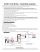
The hydronic buffer tanks are built with 4 connections. Two connections can be piped to the heat pump or boiler, and two
connections can be piped to the distribution system. If piped correctly, the tank can serve as both a thermal buffer and a
hydraulic separator. The heat pump or boiler can be hydraulically decoupled from the distribution system. The tanks are all
stainless steel construction with R-12 insulation, and an ABS jacket.
A 3/8” ID thermal well is located mid-tank. Thermistors can be inserted 3” into the well, or the well will accept the Honey-
well L4006A controls.
Buffer tanks are available in 22, 40, 60, 80, and 115 gallon capacities.
Specify 1 ¼”, 1 ½”, or 2” connections.