
User Manual


5
The buffer tanks are all stainless steel construction, insulated with a thermoplastic jacket.
WARNING
!
DO NOT use in potable water systems.
WARNING
!
Use this vessel only in hydronic heating systems. The installer must comply with all plumbing codes.
Do not operate above the temperature or pressure specied on the rating plate. Failure to comply may result in personal
injury, property damage, or death.
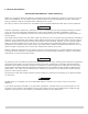
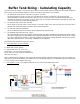
An example of piping a buffer tank follows showing a water source heat pump application. In all applications note that
the tank top tting should be piped the distribution supply line to the air purger and vent. This way the tank will be self
venting and no additional air vent is needed to install or maintain.
The objective in any application is to pipe the buffer tank such that the heating or cooling source is hydraulically
uncoupled from distribution system.
Model
Volume
(gal.)
A
Height
B C
D
Diameter
Connections
(NPT)
Max. Working
Pressure (psi)
Approx.
Ship wt.
(lbs.)
H2OBT22XXX 22 24.5 15.0 8.0 22.5 1¼" 60 35
H2OBT40XXX 40 42.0 29.0 9.0 22.5 Specify 60 87
H2OBT60XXX 60 42.0 29.5 9.5 26.5 1¼", 1½" 60 115
H2OBT80XXX 80 52.0 39.5 9.5 26.5 or 2" NPT 60 125
H2OBT115XXX 115 72.0 59.5 9.5 26.5 or 2" NPT 60 160