
Instruction Manual


8
C. Locating the water heater.
The water heater should be located in an area where water leakage from the tank or connections will not result in damage
to areas adjacent to the water heater or to lower oors of the structure. When such a location can not be avoided, a suit-
able drain pan must be installed under the water heater, and the drain pan must be connected to a drain.
The water heater should be installed as close to the boiler as is practical for easy access for service. The unit is designed
for installation on combustible ooring and in alcoves, closets, etc.
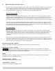
The minimum clearances from combustible surfaces are:
Bottom -------------------------------- 0”
Left, right, and rear sides ---------- 0.5”
Front -------------------------------- 0.5”
Top ------------------------------------ 6”
The minimum clearances for service are:
Bottom -------------------------------- 0”
Left, right, and rear sides ------------ 3”
Front ----------------------------------- 6”
Top ------------------------------------ 6”
D. Additional recommended components
1.
Shut-off valves. Allows the isolation of the water heater from the boiler system during service.
2.
Unions. Allows for easy locating or removal.
3.
Vacuum breaker. Protects the water heater from collapse if a hot tank is valved off to service other components
in the system.
4.
Thermal expansion tank. If the water heater is installed in a closed water supply system, such as a system
having a back ow preventer in the cold water supply line, the installation of a thermal expansion tank is
required.
E. Removing the Existing Domestic Water Heating System
1.
External Tankless Heater- Disconnect all lines to the boiler and plug the boiler ttings. Disconnect the external
heater from the boiler piping, and the domestic piping systems.
2.
Internal Tankless Heaters- Disconnect the domestic piping. Do not plug the cold water or the hot water ttings
in the internal tankless coil. Leave the coil in the boiler with the cold and hot water ttings open to prevent
pressure build-up in the coil.
WALLS
WALLS
CEILING
6" Minimum
0.5" Minimum
0.5"
Min.
Sides
0.5"
Min.
Sides
0.5"
Min.
Sides
0.5"
Min.
Sides
Top
Rear
Front
Provide access clearance
Front View Top View