P.O. Box 4729 Utica, NY 13504-4729 www.ecrinternational.com HOTLINE INDIRECT WATER HEATER MODELS HL30SK, HL40SK, HL50SK, HL80SK, HL119SK SET-UP, OPERATING & MAINTENANCE INSTRUCTION MANUAL 3 Twice the recovery of a standard gas-fired water heater and four times the recovery of an electric water heater. 3 Counterflow design increases heat transfer by 50% for better temperature mixing. 3 Unique, smooth tube heating coil resists lime buildup that commonly reduces the life of other indirect water heaters.
To the Installer: To the Consumer: Please attach these instructions next to the water heater. Please read these and all component instructions and keep for future reference. Indirect Coil Tank Water Heater Instruction Manual Warranty, Registration Card and Parts List are included. Homeowner: Please remember to return the Registration Card! WARNING INSTALLER RESPONSIBILITIES Improper installation, adjustment, alteration, service or maintenance can cause serious injury or property damage.
TABLE OF CONTENTS Section I: Specifications . . . . . . . . . . . . . . . . . . . . . . . . . . . . . . . . . . . . . . . . . . . . . 4 Section II: General Information . . . . . . . . . . . . . . . . . . . . . . . . . . . . . . . . . . . . . . . 6 Section III: Pre-Installation . . . . . . . . . . . . . . . . . . . . . . . . . . . . . . . . . . . . . . . . . . . 8 Section IV: Installation . . . . . . . . . . . . . . . . . . . . . . . . . . . . . . . . . . . . . . . . . . . . . 10 Section V: Maintenance . .
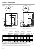
SECTION I: SPECIFICATIONS Anode Rod Hot Outlet/ Anode Rod, 3/4" NPT Hot Outlet, 1 1/2" NPT Cold Inlet, 3/4" NPT Anode Rod Anode Rod T&P Relief Valve T&P Relief Valve From Boiler Supply, 1" NPT From Boiler Supply, 1" NPT Aquastat B B C Aquastat C Drain Valve D E To Boiler Return, 1" NPT D To Boiler Return, 1"NPT G E F F Drain Valve H A G A Cold Inlet, 1" NPT Figure 2: HL80SK, HL119SK Figure 1: HL30SK, HL40SK, HL50SK Table 1: Dimensions Model A B C D E F G H D i m e n s i
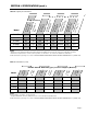
SECTION I: SPECIFICATIONS (cont.) Table 2: Capacity & Performance Con Rat tinuous ing (GP Draw H)* Firs t Rat Draw ing (gal )* 30 1.38 110 85 25 55,000 1.3 2.0 HL40SK 38 2.30 153 120 33 77,000 1.1 3.0 HL50SK 45 2.30 160 120 40 77,000 1.0 3.0 HL80SK 75 2.76 200 130 70 83,000 0.9 5.0 HL119SK 110 2.76 232 130 102 83,000 1.2 5.
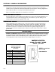
SECTION II: GENERAL INFORMATION LOCATION The indirect coil tank water heater should be located in a central location to the piping system, as close as practical to the boiler and in an area not subject to freezing temperatures. Leave sufficient space for servicing and maintaining the heater. Note: Long heating supply runs can lengthen recovery times. WATER TREATMENT/FILTRATION In areas where poor water conditions are suspected (i.e.
SECTION II: GENERAL INFORMATION (cont.) ANODE RODS The anode rod is used as a sacrificial element within the volume of the storage tank. The purpose of the magnesium anode rod is to protect the inside of the tank against corrosion. Anode rods should be inspected twice in the first year and at least yearly once a time interval for inspection has been developed. Water conditions can influence the consumption rate of the anode rods.
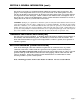
SECTION III: PRE-INSTALLATION BOILER AND CIRCULATOR SIZING The ratings published in this manual for your HotLine Indirect Coil Tank Water Heater can be obtained through proper selection of boiler output and circulator capacity. As noted, the ratings in Table 2 are based on a 77°F rise with 58°F potable water inlet temperature at a circulator pump flow rate of 8 GPM. The boiler was set at 180°F.
SECTION III: PRE-INSTALLATION (cont.) UP 15-42F/FR Closed Systems, 60 Hz Figure 4: GRUNDFOS UP 15-42F performance curve UP 26-64F Closed Systems, 60 Hz Figure 5: GRUNDFOS UP 26-64F performance curve Note: Zone valves on the heat source supply to the indirect heater are not recommended and will drastically reduce performance. System performance can also vary based on the heating capacity of the boiler.
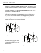
SECTION IV: INSTALLATION WATER CONNECTIONS All piping between the boiler and the indirect heater should be new copper with a minimum size of 3/4” ID for models HL30SK, HL40SK, and HL50SK. Use 1” minimum copper for models HL80SK and HL119SK. Elbows should be minimized. A flow check valve must be installed on the return line. All piping to the inlet (cold) and outlet (hot) domestic water connections should be new copper with a minimum size of 1/2” ID for models HL30SK, HL40SK, and HL50SK.
SECTION IV: INSTALLATION (cont.) See Figure 8 for piping your HotLine Indirect Coil Tank Water Heater to a low-mass boiler (diagram recommended by boiler manufacturer).
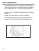
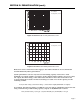
SECTION IV: INSTALLATION (cont.) ELECTRICAL CONNECTIONS Figure 9: Boiler Maintaining 180°F Figures 9 and 10 are general wiring diagrams. For a maintaining temperature boiler, Figure 9 should closely match your system. For cold start boilers your wiring may resemble Figure 10, but will vary depending on the boiler type and controls or relays used. It is not possible to list all wiring variations here.
SECTION V: MAINTENANCE WATER PIPING On an annual basis, all piping should be checked for leakage at joints, shut-off valves, and unions. T&P RELIEF VALVE On an annual basis, the temperature and pressure relief valve should be checked for proper operation. First, attach a drain line to the valve to direct the water discharge to an open drain. This is very important because the temperature of the discharge could be very hot. Second, lift the lever at the end of the valve several times.
SECTION VI: TROUBLESHOOTING PROBLEM CAUSE No hot water at faucet Boiler does not operate Circulator does not operate Improper aquastat setting Electrical problem (relay, wiring, etc.
SECTION VII: PARTS LIST # Item # Qty 1 1 1 2 2 2 3 3A 4 5 5 6 6 7 8 9 10 11 12 13 14 15 ST00301 ST00701 ST00901 ST00401 ST00801 ST01301 1 2 2 1 1 1 ST00601 ST01001 1 1 ST01101 1 INDIRECT COIL TANK WATER HEATERS HL30SK, HL40SK, HL50SK, HL80SK, HL119SK Description Magnesium Anode Rod 3/4" x 30" Magnesium Anode Rod 3/4" x 36" Magnesium Anode Rods 3/4" x 40" Dip Tube 3/4 x 3 x 33" Dip Tube 3/4 x 3 x 44" Dip Tube 3/4 x 3 x 38" Nipple 3/4 x 3", Hot Out or T&P Nipple, 1 1/2" Cap, Magnesium Anode Rod Lea
SECTION VIII: WARRANTY LIMITED LIFETIME WARRANTY GENERAL CONDITIONS Hot Line Water Heaters, ECR International, warrants that the Hot Line tank shall be free of defects in material and workmanship during normal use and service for as long as the original residential purchaser owns the home in which the unit was originally installed. For the purposes of this Limited Warranty, residential purchaser is defined as the owner of a single family home in which the purchaser resides on a permanent basis.