
Instruction manual


Page 10
BOILER
SYSTEM
SUPPLY
CIRCULATOR
PUMP
BOILER
SYSTEM
RETURN
BOILER
COLD
1"
INLET
WAT ER HEATER
INDIRECT
HOT OUT
DOMESTIC
1 1/2"
BOILER
FROM
TO
BOILER
CHECK
VALVE
B
OILER
S
UPPLY
SYSTEM
DOMESTIC
3/4"
HOT OUT
INDIRECT
WAT ER HEATER
BOILER
TO
BOILER
FROM
COLD
INLET
3/4"
VALVE
CHECK
PUMP
CIRCULATOR
RETURN
S
YSTEM
BOILER
BOILER
1" NPT
1" NPT
1" NPT
1" NPT
BOILER
SYSTEM
SUPPLY
CIRCULATOR
PUMP
BOILER
SYSTEM
RETURN
BOILER
COLD
1"
INLET
WAT ER HEATER
INDIRECT
HOT OUT
DOMESTIC
1 1/2"
BOILER
FROM
TO
BOILER
CHECK
VALVE
BOILER
SUPPLY
SYSTEM
DOMESTIC
3/4"
H
OT OUT
INDIRECT
WAT ER HEATER
B
OILER
T
O
BOILER
F
ROM
COLD
INLET
3/4"
VALVE
CHECK
PUMP
CIRCULATOR
RETURN
SYSTEM
BOILER
BOILER
1" NPT
1
" NPT
1" NPT
1" NPT
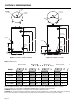
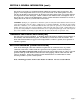
Figure 7: HL80SK, HL119SK water connections
SECTION IV: INSTALLATION
WATER CONNECTIONS
All piping between the boiler and the indirect heater should be new copper with a
minimum size of 3/4” ID for models HL30SK, HL40SK, and HL50SK. Use 1” minimum copper
f
or models HL80SK and HL119SK. Elbows should be minimized. A flow check valve must be
installed on the return line.
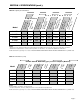
All piping to the inlet (cold) and outlet (hot) domestic water connections should be new
copper with a minimum size of 1/2” ID for models HL30SK, HL40SK, and HL50SK. Use 3/4”
ID minimum for models HL80SK and HL119SK.
All piping should conform to local codes and ordinances. At a minimum, refer to IHLR 84
code if local codes are not in place. It is recommended that all piping be adequately
insulated with approved material to ensure minimum heat loss. If a re-circulation line is
used for domestic water, be certain that all lines are well insulated and the circulator is
temperature controlled. Install isolation valves to permit proper servicing. It is also
recommended to install a union on the domestic outlet to facilitate replacement of the hot
outlet / anode nipple on models HL30SK, HL40SK, and HL50SK.
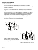
See Figures 6 and 7 for proper water connection installation.
HL
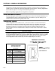
Note: Indirect may be connected to a steam
boiler pr
ovided that all piping to and fr
om
the boiler are below the water line of the boiler.
Boiler must also be protected by a low water
cut of
f safety device.
Figure 6: HL30SK, HL40SK, HL50SK
water connections