
Instruction manual


Page 4
G
C
old Inlet,
3
/4" NPT
Hot Outlet/
Anode Rod,
3
/4" NPT
A
node
Rod
Aquastat
T
&P Relief
V
alve
F
rom Boiler
Supply, 1" NPT
T
o Boiler
Return, 1"
N
PT
Drain
Valve
F
D
C
E
B
A
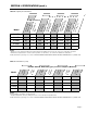
SECTION I: SPECIFICATIONS
Foam insulation standard on Indirect models. Pressures, all: Test pressure, 300 PSI Working pressure, 150 PSI
Standard voltage, all: 120V, 60Hz, 1P. T&P valve installed; nipples supplied for top connection.
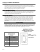
W
ARNING:
Installation should be in accordance with all national and/or local codes.
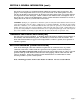
CAUTION: The r
ecommended water temperatur
e setting for normal residential use is 120°F. ECR recommends a tempering
valve or anti-scald valve be installed and used according to the manufacturer's directions to prevent scalding.
HL30SK
22´´
35
3
⁄4´´ 27
3
⁄4´´ 19
1
⁄2´´ 11
3
⁄4´´ 6
1
⁄2´´ 4
1
⁄2´´ n/a
HL40SK 22´´ 42
3
⁄4´´ 34
3
⁄4´´ 31
1
⁄2´´ 16
3
⁄4´´ 6
1
⁄2´´ 4
1
⁄2´´ n/a
HL50SK 22´´ 48
3
⁄4´´ 39
3
⁄4´´ 31
1
⁄2´´ 16
3
⁄4´´ 6
1
⁄2´´ 4
1
⁄2´´ n/a
HL80SK 24
´´
64
3
⁄4´´ 57
1
⁄8´´ 33
´´
19
1
⁄4´´ 8´´ 5´´ 5´´
HL119SK 28´´ 65
1
⁄4´´ 57
3
⁄4´´ 33
3
⁄4´´ 16
1
⁄4´´ 8
3
⁄4´´ 5´´ 6
1
⁄2´´
Model
A
B
C
D
E
F
G
H
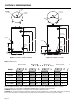
Table 1: Dimensions
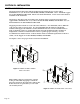
G
H
A
E
F
D
C
B
Cold Inlet,
1" NPT
Hot Outlet,
1 1/2" NPT
Anode
Rod
Anode
Rod
T&P Relief
Valve
From Boiler
Supply, 1" NPT
To Boiler
Return,
1"NPT
Drain
Valve
Aquastat
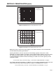
Figure 2: HL80SK, HL119SK
Dimensions
Figure 1: HL30SK, HL40SK, HL50SK