XEB Series II Gas=Fired Hot Water Induced Draft Boilers Hodels XEB-2 XEB-3 XEB-4 XEB-5 XEB-6 XEB-7 INSTALLATION,OPERATION& MAINTENANCEMANUAL ...::::::::::::::::::::::::::::::::::::::::::::::::::::::::::::::::::::::::::::::::::::::::::::::::::::::.L....' ..................................................................................................................................................................... ::,,::,,::,,,,,,_,,_ f,r_ "4__,,rS P, IIII ............................................
Boiler Ratings & Capacities ...................... Dimensions ............................................. 4 Installation Procedure 5 Ventilation Installation Vent System Installation Horizontal Venting Piping Sequence of Operation Starting Your Checking Maintaining Service Your Equipment Appendix A.1 Installation A.2 Electrical Connections A.3 Adjusting A.4 Display A.5 Operation A.6 Boiler Settings ......................... 28 ........
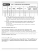
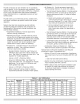
Table 1 - RATINGS NATURAL AND PROPANE GASES Vent Diameter Model Heating Capacity Znput ! *Mbh ! *Mbh AHRI ! ** Net Rating Water *Mbh (Inches) AFUE To Chimney ! ! (Category Z) ! Horizontal Vent (Category HI) XEB-2 42.5 36 31 84.4 4 3 XEB-3 75.0 63 55 83.4 4 3 XEB-4 112.5 94 82 83.0 4 3 XEB-5 150.0 125 109 82.7 4 3 XEB-6 187.5 155 135 82.3 4 4 XEB-7 225.0 186 162 82.0 4 4 * MBH = 1,000 Btuh = British Thermal Unit Per Hour.
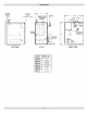
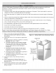
ASME CONTROL PANEL _Uy _ocated} REUEF VALVE SUPPLY DRAIN VALVE 29 ( GAS VALVE Le_ Side Right Model Width (A) XEB=2 11 XEB=3 14-1/4 XEB=4 17-1/2 XEB=5 20-3/4 XEB=6 24 XEB=7 27-1/4 Side
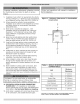
Improper installation,adjustment,alteration, service or maintenancecould result in deathor serious injury. Followlocal regulationswith respectto installation of COdetectors. 1. Installationmustconformto requirements of authority havingjurisdictionor, in absenceof suchrequirements, Figure i - Minimum Clearances To Combustible Construction to the NationalFuelGasCode,ANSIZ2231/NFPA 54 2.
Provide combustion air and ventilation air in accordance with the section "Air for Combustion and Ventilation," of the National Fuel Gas Code, ANSI Z223.1/NFPA 54, or Sections 8.2, 8.3 or 8.4 of Natural Gas and Propane Installation Code, CAN/CSA B149.1, or applicable provisions of local building codes. • All Outdoor Air. Provide permanent opening(s) communicating directly or by ducts with outdoors. Two Permanent Opening Method.
Burn or Scald Hazard. Discharge line shall be installed to relief valve outlet connection to avoid scalding, or water damage due to discharge of steam and/or hot water during operation. Discharge burns, line shall: • connect to relief valve outlet and piped down to safe point of disposal. distance from floor or allowable safe point of discharge.
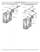
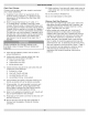
Figure 3 = Forced Hot Water Typical CIRCULATOR COLD Piping Figure 4 = Forced Hot Water Typical With Zone Control Valve Piping m...,,...
• Install radiation units (panels, radiators or cabinets) and supply and return mains first then make connections at boiler. • Verify clean water cold water supply pump when water • Provide low water supply is available when connecting to water valve. Install sand strainer at supply is from well or pump. cutoff device when boiler is installed above radiation level or as required by the Authority having jurisdiction, either provide as part of boiler or at time of boiler installation.
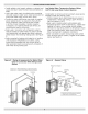
Check Your Chimney Chimney must be clean, right size, properly constructed and in GOOD CONDITION. lo o Installation must conform to requirements of the authority having jurisdiction or, in absence of such requirements, to the National Fuel Gas Code, ANSI Z223.1/NFPA 54. 12. Do not connect to fireplace flue. Boiler's induced draft blower has 3" outlet. 3" X 4" increaser fitting is included in parts bag.
Figure 7 - Type B Gas Vent Liner Chimney Sheet Metal Firestop Vent System C[eanout CHECK YOUR CHIMNEY For boilers for connection to gas vents or chimneys, vent installations shall be in accordance with "Venting of Equipment", of the National Fuel Gas Code, ANSI Z223.1/NFPA 54, or applicable provisions of the local building codes.
Removing System Existing Boiler From Common Venting When an existing boiler is removed from a common venting system, the common venting system is likely to be too large for proper venting of the appliances remaining connected to it. At the time of removal of an existing boiler, the following steps shall be followed with each appliance remaining connected to the common venting system placed in operation, while the other appliance remaining connected to the common venting system are not in operation. 1.
Horizontal (CategoryIll)venting systems must be installed in accordance with these instructions, CHOICE OF VENT PIPE MATERIAL • U. L.ListedZ-FlexZ-VentStainless SteelVent Pipe. Maximum Horizontal Vent Length For Stainless Steel Vent Pipe - 30' Plus One 900 Elbow Plus Vent Terminal, Minimum Horizontal Vent Length - 2.
Boilers may be vented horizontally as shown in Figure 8, Page 13. Vent pipe is pitched down from boiler to vent termination. Do not connect other appliances to this vent. lo o o Vent Termination Fitting: For all vent pipe materials, you may use either: A. Vent Pipe Material: A. UL Listed Z-Flex Z-Vent stainless steel vent pipe from boiler to vent termination, -or- -orB. UL Listed Heat-FabSaf-T-Vent stainless steel vent pipe from boiler to vent termination, C.
Figure 9 - Horizontal Venting Clearances Note: If there is a potential for excessive winds, special consideration should be given to locate the vent termination away from the windward side of the building, Vent Cap must be at least 7' (2,13m) above any public walkway Mount vent cap at least 3' (0.9m) from inside corners. Vent cap must be at least 3' (0.9m) above and 10' (3m) from any forced fresh air inlet. Vent cap must 4' (1.2m) from or below any doors, windows or gravity air inlet.
o Joining and Sealing the Vent Pipe: The vent pipe needs to be both watertight and gas tight. Seal all joints and seams as follows: A. For Z-Flex Z-Vent stainless steel vent pipe use a high temperature silicone sealant rated for 550°F. The outside of the male end and inside of the female end of the pipe must be cleaned with brake cleaner before applying silicone bead. For 3" vent pipe runs begin with the male end of the vent pipe over the boilers induced draft blower outlet.
C. For Flex-L StaR-34 stainless steel vent pipe use a high temperature silicone sealant rated for 550°F. Before applying silicone, the outside of the male end and inside of the female end of the pipe must be cleaned using a cleaner, such as methyl ethyl ketone (MEK) or naphtha. For 3" vent pipe runs, begin with the male end of the vent pipe over the boiler's induced draft blower outlet. For 4" vent pipe runs begin with a StaR-34 3" to 4" increaser fitting over the boiler's induced draft blower outlet.
o Support Spacing: Do not restrict thermal expansion movement of the vent. The vent pipe must expand and contract freely with temperature change. Each run of vent piping shall be supported as follows: A. Z-Flex stainless steel vent piping requires a loose fitting metal strap or similar support at each joint at a maximum of 4 feet between supports. B. Heat=Fab stainless steel vent piping requires a support for every 6 feet of horizontal piping run.
Connecting _t_ CAUTION WHAT TO DO IF YOU SMELL GAS • Do not try to light any appliance. • Do not touch any electrical any phone in your building. switch; do not use • Immediately call your gas supplier from neighbor's phone. Follow gas supplier's instructions. • If you cannot department. Figure reach your gas supplier, a call the fire Gas Piping Gas line enters boiler from right side. Flexible gas connectors must never breach any boiler openings.
92,000 190,000 350,000 625,000 40 63,000 130,000 245,000 445,000 60 50,000 105,000 195,000 365,000 *Outside diameter: Measure length of pipe or tubing second stage regulator.
Electric Electrical shock hazard. Turn OFF electrical power supply at service panel before making electrical connections. Failure to do so could result in death or serious injury. Electrical Wiring See wiring diagram Figure 12, Page 23 for details. Refer to Ladder Diagram from document envelope received with boiler.
Sequence of Operation =See Figure 12, Page 23 1. Thermostat calls for heat, control relay contacts. 2. Circulator pump is powered through terminals C1 and C2. Control holds off burner and attempts to satisfy thermostat with residual boiler heat. 3. Induced draft blower and transformer powered. 4. When blower gets up to speed and blower suction pressure reaches pressure switch set point, pressure switch contacts close sending 24 volts to pilot control from transformer secondary. 5.
Figure 12 - Control Module SPARK IGNITER_ ( I FLAME _ SENSE LI ® ® D TRANSFORMER 24VAC CAMPER o0,0 _ _!D _ENVIRACOM1 _ _ GAS CONTROL 0 / ° D u__ m N_ D_ _ D m _ _D __ _ BE _B NN @ ©©©©__ /_I\ OPTIONAL DEPENDING LIMIT SWITCH PRESSURE SWITCH SENSOR1 _D m _ ON CONFIGURATION Damper isnotan option.
Do not add water into hot empty boiler. Filling System With Water • Close air vents on all radiation units. Open valves to these units. • Verify boiler and expansion tank drain valves are closed. Air bleed screw on tank drain fitting should be closed. • Open valve in line from boiler to expansion tank. • Open water inlet to your boiler and leave open. • Start with lowest radiation unit. Open air vent on this unit. When all air has escaped and water starts to flow from vent, close it.
Operating If you do not follow these instructions exactly, a fire or explosion may result causing property damage, personal injury or loss of life, • This appliance is equipped with an ignition device which automatically lights burner. Do NOT try to light this burner by hand. • Before operating smell all around appliance area for gas. Be sure to smell next to floor because some gas is heavier floor. 1. Instructions. STOP! Read Safety Information :2. Set the thermostat on previous page.
Gas Valve Safety Shutdown Electrical shock hazard. Test Follow instructions Figure to turn off electric power. Failure to do so could result death or serious injury. in 14 PRESSURE (UNDER - Automatic REGULATOR Gas Valve WERING TERMINALS (2) ADJUSTMENT CAP SCREW) OUTLET PRESSURE TAP INLET PRESSURE TAP \_, Ignition system safety shutoff device must be tested after placing boiler in operation. With main burners firing, disconnect ignition cable from intermittent pilot control box.
Figure 16 -Hain Burner Flame Adjust Thermostat Heat Anticipator Instruction for final adjustment with thermostat. 1. Set Heat anticipator of thermostat are packaged at .2. :2. Check thermostat operation. When set above temperature indicated on thermometer, boiler burners should ignite. Verify thermostat turns off boiler when room temperature reaches selected setting and starts boiler operating when room temperature falls few degrees.
Burners Cleaning Your Boiler And Burners Beginning of heating season visually check pilot end main burner flames. See Figures 14, 15 & 16 Pages 26 & 27. Flue passages between sections should be examined yearly and cleaned if necessary, To clean: Safety Relief Valve Test safety relief valve for proper operation.
You may avoid inconvenience and service calls by checking these points before you call for service: I CAUTTON WHAT TO DO IF YOU SMELL GAS • Do not try to light any appliance. • Do not touch any electrical switch; do not use any phone in your building. • [mmediately call your gas supplier from a neighbor's phone. Follow the gas supplier's instructions. • If you cannot reach your gas supplier, call the fire department.
AIR ELIMINATING Burn and scald hazard. Safety relief valve could discharge steam or hot water during operation. Install discharge piping per these instructions. SAFETY RELIEF VALVE [Figure 2, Page 7] Safety relief valve is required on your boiler, Water expands as it is heated. If there is no place for water to expand into, water pressure will build up inside boiler and system. Should this happen, safety relief valve will automatically open at predetermined pressure.
PRESSURE SWITCH Air pressure switch works on negative pressure. When blower comes on air pressure switch operates intermittent pilot and gas valve. Air pressure switch is factory set and will only work when blower operates properly. It will not allow boiler to come on if blower does not generate enough pressure or if venting system is blocked. Factory Pressure Switch Set point: -0.4" wc. for 2-5 section boilers. -0.5" w.c. for 6-7 section boilers.
A.:I. Installation Environment Considerations A,3 Adjusting Settings To discourage unauthorized changing of settings, procedure to enter adjustment mode is required. If you do not follow these instructions exactly, a fire or explosion may result causing property damage, personal injury or loss of life, • Do not use this appliance if any part has been under water.
A,5 Operation 2. Control determines burner operation is required, module proceeds to start burner (see state codes list) and heats water in boiler until setpoint temperature is achieved or thermostat is satisfied,, 3. Burner is de-activated, ignition module completes heating cycle, returns to idle and waits for temperature to drop again, 4. Circulator is turned on throughout Module continuously monitors boiler water temperature and fires or shuts off burner based on this temperature data, 1.
A.6 Boiler High Limit Temperature • When water temperature ends heating cycle. Controller reaches setpoint, controller A.7 Troubleshooting • Following service procedures are provided as general guide. • When water temperature drops below setpoint minus differential, controller restarts heat cycle to re-heat boiler water. On lockout and retry models, meter readings between gas control and ignition module must be taken within trial for ignition period.
Error ...... Code Definition Consequence Number 2 Pressure switch failed to open (stuck closed).
STEP3: Checksparkignitioncircuit, Electricalshockhazard.Ignition circuit generates over 10,000volts. TurnOFFelectricalpower supply at servicepanelbeforemaking electrical connections. Failureto do so could result in death or serious injury. Disconnect ignitioncableat SPARK terminalonmodule. Energize moduleandlistenfor audiblesparkingnoise. Whenoperatingnormally,thereshouldbebuzzingnoise turnsonandofftwicepersecondfor durationof 1-7 seconds,depending onmodel. STEP4: Verifypilotandmainburnerlightoff.
NOTES
DUNKIRK BOILERS 2201 Dwyer Avenue, Utica NY 13501 web site" www.ecrinternational.