
Install Instructions
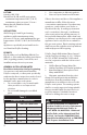
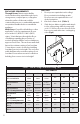
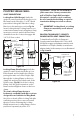
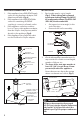
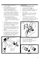
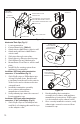

Figure 3a
LOCKING
TAB
LOCKING
BAND RECESS
1/4"
CLICK!
LOCKING
BAND CLASP
VERIFY GASKET IS
SEATED IN FEMALE
END OF PIPE
Figure 3b
NEW
LOCKING
CLAMP
TIGHTEN HOSE
CLAMP TO SECURE
JOINT
VERIFY LOCKING
CLAMP HOOKS
UNDER GASKET
EXTRUSION
POLYPRO SINGLEWALL
JOINT CONNECTIONS
Locking Band (Old Design): Verify the
gasket is seated evenly inside the groove in
the female end of the pipe. For PP / Metal
pipe with a locking tab, slide the Locking
Band on to the male pipe section Fig.3a.
Insert locking tab into locking band recess,
rotate button away from locking band clasp,
insert pipe sections, push lock band clasp
downward over the socket, disengage tab
1/4"-5/8" from socket.
Locking Clamp (New Design): Verify the
gasket is seated evenly inside the groove
in the female end. Assemble the joint by
passing the male end of the Polypro Pipe
through the Locking Clamp on the hose
clamp side and into the female end of the
PolyPro pipe, (Fig.3b). Hook the Locking
Clamp onto the gasket extrusion on the
female end and tighten down on the hose
clamp.
The new Locking Clamp design is
backwards compatible with pipe sections
designed for use with the Locking Band.
Use pliers to break o the Locking Tab with
a twisting motion. Once removed, install
the pipe section following the Locking
Clamp instructions. Locking Clamps can be
purchased separately in packs of 12.
Fig.3a and b. Screws are not allowed for
joint connection. Never penetrate the
wall of PolyPro Single-Wall vent pipe.
(Exception: a stainless steel screw may
be used outside the building on exterior
termination ttings to orient an elbow,
etc).
• IMPORTANT: Locking Bands or Locking
Clamps are mandatory on all exhaust
vent joints
POLYPRO TO DURAVENT / SECURITY
CHIMNEY METAL VENT CONNECTION
To transition from PolyPro to Duravent /
Security metal vents that are UL 1738 or ULC
636 listed, an approved adapter must be used.
Installation of PolyPro (female) to metal vent
adapter (male) is the same process as illustrated
in Fig.3a and b.
7