
Install Instructions

9
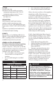
MAX
5FT
1.5m
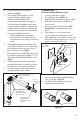
ATTACH WALLSTRAP 1" TO 12"
FROM LOCKING BAND
3/8" ALL
THREAD
LOCKING CLAMPS
OR BANDS ARE
REQUIRED AT EVERY
EXHAUST JOINT
WALLSTRAP
MINIMUM 1PER
HORIZONTAL PIPE
SECTION
MAX
10FT
3M
Figure 8
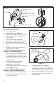
Figure 9
ALIGN TABS WITH
MOUNTS
GASKET
EXTERIOR
WALL PLATE
INTERIOR
WALL PLATE
TERMINATIONS
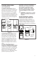
Horizontal Single-Wall Pipe (Fig.9)
1. Locate penetration in wall.
2. Cut and frame hole. (Table 3)
3. Attach Interior Wall Plate to interior wall.
4. Attach and seal Exterior Wall Plate to
exterior wall.
5. Line up keyway, slide black pipe (UV
Protected) or termination through
plates.
6. If termination is used, attach with
screws. Align tabs with pipe mounts.
7. Add additional components to raise vent
level if desired (vent must be 12" above
grade or average snow level).
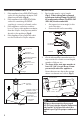
8. Remove gasket and install Bird Guard
into end of pipe. (Fig.10)
9. Install Poly Pro venting system from
appliance to termination.
Figure 10
REMOVE GASKET
INSERT BIRD GUARD
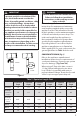
4. Every horizontal vent run must be
supported. (Fig.8)
5. The venting system shall be securely
supported using suitable hangers.
Supports made by DuraVent are
recommended; eld supplied supports,
such as all-thread or plumbers tape, that
are approved by the AHJ is acceptable. All
supports must not deform or damage the
vent. Ensure the load of the vent system is
not supported by the appliance.
• Duravent Wallstraps are designed
for use with 3/8”-16 all-thread rod to
extend from a wall, ceiling, or anchoring
point.
6. Vertical pipe lengths must be supported
every 10 feet (3 meters) or less. Horizontal
pipe lengths must be supported every 5
feet (1.5 meters) or less. (Fig.8)
7. Elbows and Tees are suciently supported
by attaching a wall support within 1" to 12"
of the pipe joint holding the Elbow or Tee.
(Fig.8)
8. Vertical components can be insulated in
unconditioned space or when run outside.
Use mineral wool or housing insulation.
9. Use black UV protected components on
venting installed on the outside.