
Installation Guide
A MAJOR CAUSE OF VENT
RELATED FIRES IS FAILURE
TO MAINTAIN REQUIRED
CLEARANCES (AIR
SPACES) TO COMBUSTIBLE
MATERIALS. IT IS OF THE
UTMOST IMPORTANCE THAT
DURABLACK BE INSTALLED
ONLY IN ACCORDANCE WITH
THESE INSTRUCTIONS.
NOTE:
Read through all of these instructions
before beginning your installation. Failure
to install as described in this instruction
will void the manufacturer’s warranty, and
may have an effect on your homeowner’s
insurance. Keep these instructions for
future reference.
NOT A UL LISTED PRODUCT
Dear Customer, Installer, or End User:
We welcome any comments, ideas, input or
complaints regarding DuraVent products.
If you are searching for tech support or product
information, please phone us at 800-835-4429.
Or email us at:
techsupport@duravent.com
IMPORTANT
DuraBlack must be installed with at least an
18” Clearance to Combustibles.
Read all instructions carefully before starting
the installation. The DuraVent warranty will be
voided, and serious re, health, or other safety
hazards may result from any of the following
actions:
• Installation of any damaged DuraBlack
component.
• Unauthorized modication of any
DuraBlack component
• Installation of any component part not
manufactured or approved by DuraVent.
• Installation other than as instructed
by DuraVent and the appliance
manufacturer. Consult your local building
codes before beginning the installation.
INSTALLATION PROCEDURE
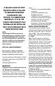
Prior to beginning your installation, please
verify what style connector pipe you have. You
may have "Locking Tab" style, or "Trim Ring"
style per Fig.1. These are the methods for
attaching your connector pipe to the support
box (Fig.2).
Step 1. Insert the adapter or Connector
section of pipe into the previously installed
Ceiling Support Box. Position it so the seams
are facing the wall, and the smooth side is
facing the room. For "Locking Tab" connectors,
push the pipe in rmly, until the locking notches
engage the top of the rim of the hole in the
support box. For "Trim Collar" style connector,
insert the pipe into the support box. Slide the
trim collar on and slide up to the support box,
until it is next to the pipe bead. Using the four
pre-punched holes in the trim collar as a guide,
drill 1/8" diameter holes in the support box, and
afx using the sheet metal screws provided. It
is extremely important that the Support Box
be positioned so that the single wall pipe is
at least 18” from the combustible wall, and
also that the support box protrudes at least
2” below the ceiling.
Reposition the Support Box if necessary, to
meet these two requirements.
Step 2. If you have "Locking Tab" style
connectors and you are installing the optional
Trim Collar, slide the Trim Collar upwards over