
Install Instructions


INSTALLATION
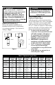
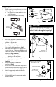
1. PolyPro vent pipe lengths may be cut to
length. (Fig.6)
• Cut square (not at an angle) to the
end of the pipe.
• Remove burrs before assembly.
Figure 6
MARK
CUT WITH
HACKSAW
DEBURR
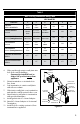
Figure 8
ALLTHREAD
WALL STRAP
MINIMUM 1PER
HORIZONTAL PIPE
SECTION
LOCKING BANDS
REQUIRED AT EVERY
EXHAUST JOINT
MAX
10FT
3m
7
Figure 9
ALIGN HOOK TO GAP
SECURE ANCHOR
BOLT TO SUPPORT
VENT SYSTEM
ALTERNATE PP WALL STRAP
CAN BE INSTALLED ON FEMALE
END OR BODY OF PIPE
ALIGN WALL STRAP
WITH KEYWAY
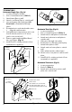
Figure 7
12"
5/8"
MIN
1/4" 5/8"
7.5mm 15mm
TO APPLIANCE
2. Check with appliance manufacturer for
any restrictions or limits on vent length,
number of elbows, etc.
3. The slope of the vent pipe must be at
least 5/8" rise per foot (50mm rise per
1m) away from the appliance, (Fig.7).
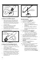
4. Wall Straps are required to support the
overall vent run.
Make sure that the load
of the vent system is not supported by the
appliance .
(Fig.7, 8, and 9)
• All-thread may be used as an
extension to the wall strap
5. Vertical installations must be supported
every 10 feet (3 meters) or less,
(Fig.8 & 9)
6. Every horizontal section must be
supported. (Fig.8)
7. Elbows and Tees are suciently supported
when a bracket is xed at the female end of
the connected straight section (Fig.8).
8. Vertical components can be insulated in
any unconditioned space or when ran
outside
9. Only black UV treated components can be
installed outside
PP Pipe sections must be disengaged 1/4"-
5/8" per joint (to allow for expansion) and
sloped 3° back to the appliance per Fig.7
for proper condensate flow.
IMPORTANT