888 Special Sewing Machine Instruction manual Postfach 17 03 51, D-33703 Bielefeld • Potsdamer Straße 190, D-33719 Bielefeld Telefon +49 (0) 521 / 9 25-00 • Telefax +49 (0) 521 / 9 25 24 35 • www.duerkopp-adler.com Ausgabe / Edition: 10/2014 Änderungsindex Rev. index: 04.0 Printed in Federal Republic of Germany Teile-Nr./Part.-No.
All rights reserved. Property of Dürkopp Adler AG and copyrighted. Reproduction or publication of the content in any manner, even in extracts, without prior written permission of Dürkopp Adler AG, is prohibited.
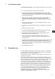
Foreword This instruction manual is intended to help the user to become familiar with the machine and take advantage of its application possibilities in accordance with the recommendations. The instruction manual contains important information on how to operate the machine securely, properly and economically. Observation of the instructions eliminates danger, reduces costs for repair and down-times, and increases the reliability and life of the machine.
General safety instructions The non-observance of the following safety instructions can cause bodily injuries or damages to the machine. 1. The machine must only be commissioned in full knowledge of the instruction book and operated by persons with appropriate training. 2. Before putting into service also read the safety rules and instructions of the motor supplier. 3. The machine must be used only for the purpose intended. Use of the machine without the safety devices is not permitted.
Contents Page Introduction and safety instructions Part 1: Operating Instructions Class 888 - Original Instructions (Edition 10/2014) 1 Product description . . . . . . . . . . . . . . . . . . . . . . . . . . . . . . . . . . . . . . . . . . . 5 2 Designated use . . . . . . . . . . . . . . . . . . . . . . . . . . . . . . . . . . . . . . . . . . . . . . 5 3 3.1 3.2 3.3 Subclasses and sewing equipment Subclasses . . . . . . . . . . . . . . . . . . . . . . . . . . . . . . . . . . . . . . . . . . . .
.17 6.17.1 6.17.2 6.18 Upper oblique edge trimming control . . . . . . . . . . . Switching on/off edge trimmer . . . . . . . . . . . . . . . Material guide adjustment . . . . . . . . . . . . . . . . . . Disengaging the needle bar with subclass 888-460522 . . . . . . . . . . . . . . . . . . . . . . . . . . . . . . . . . . . . . . . . . . . . . . . . . . . . . . . . . . . . . . . . . . . . . . . . . . . . . . . . . . . . . . . . . . . . 38 38 39 40 7 7.1. 7.1.1 7.1.2 7.
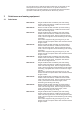
1 Product description The Dürkopp Adler 888 is a special sewing machine for universal use. 2 • • It is a double lockstitch post bed sewing machine. • Depending on subclass, the machine is either single needle or double needle unit with automatic functions such as thread trimming, automatic backtacking, automatic foot lifting, or without them. • The single needle machine can be equipped with lower or upper oblique edge trimming.
As manufacturers of industrial sewing machines we proceed on the assumption that personnel who work on our products will have received training at least sufficient to acquaint them with all normal operations and with any hazards which these may involve. 3 Subclasses and sewing equipment 3.1 Subclasses 6 888-160020 Single-needle double lockstitch post bed sewing machine with feed wheel, needle feed with driven roller foot and large hook.
888-356152 Single-needle double lockstitch post bed sewing machine with feed wheel, needle feed with driven roller foot and regular hook, electro-magnetic thread cutter, electro-magnetic seam bartacking and sewing foot lifting, equipped with electro motor driven edge trimmer. Short stitch equipment: By pressing a key on the machine head a complete stitch with shortened stitch length is sewn.
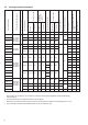
1,0 - 1,2 888-E7/1,5 - 1,5 888-E8/1,2 1,2 - 1,6 - 2,0 - 1,6 - 2,0 - 0,01mm - - mm 1/min 1/min mm mm 70-80 80 80-60 60 4 3000 2500 Scope 0,01 mm 0,6 888-E2 888-E3 0888 160020 0888 160023 0888 160122 0888 160522 888-E4/0,8 888-E5/1,0 888-E6/1,2 0888 356020 0888 356122 medium 90-110 90 50-30 40 5 2500 2500 heavy *** 120-160 120 25-10 20 7 2000 1600 light 70-80 80 80-60 60 4 3000 2500 medium 90-110 90 50-30 40 5 2500 2500 1 1 1,2 25 heavy
2 888-E30/1,6 35 2,0 - 2,4 - 1/min 1/min mm mm 5 40 2500 Machine noise ** - Wheel feed tooth pitch 1,6 Top roller diameter 25 Standard * Sewing speed mm mm 4 50-30 mm Maximum 90 - Maximum stitch length 90-120 medium Standard 90 Scope Polyester thread label number Needle number Standard 90-110 - Trimming distance from the needle 0888 260023 888-E21/2,4 0888 260122 0888 260522 0,01mm Seam distance 888-E20/2,0 0888 260020 Scope Sewing category Number of needles For c
Trimming distance from the needle 25 1,2 2,0 - 2,0 - 2,4 - 1/min 1/min mm mm 888-E54/2,0 4 888-E55/2,0 0888 260020 888-E56/2,4 0888 260023 0888 260122 888-E57/2,4 0888 260522 medium 90-110 90 60-30 40 2 2500 2500 5 35 0,6 heavy 120-140 120 25-10 20 5 2000 1600 2,4 - 888-E64/2,0 medium 90-110 90 60-30 40 5 2500 2500 2,0 - 888-E58/0,8 light 70-80 80 80-60 60 3 3000 2500 - 0,8 888-E59/1,0 medium 90-120 100 50-30 40 5 2500 2500 - 1,0 heavy 120
3.3 Sewing equipment special Machine with edge trimming When changing a sewing category, it is also necessary to replace a throat plate insert (it can be bought additionally). At the same time, when the insert is replaced, the edge width of the trimmed material is changed too, so it is necessary to change the lateral setting of the trimming knife (Service manual, section 8.4).
Types of trimming knives SINTERED CARBIDE Trimmed material thickness 1-4 1,5 - 4 1-2 0,2 - 0,8 ~6 ~6 ~4 ~6 2,4 2,4 1,2 2,4 Min. radius of trimmed material Knife lifting The standard upper knife made of tool steel is marked “A“. This type of knife can be also purchased as a type made of sintered carbide for a longer service life. To cut very small radiuses, it is possible to use a knife of the “B“ type; and for thin and soft materials it is possible to order the “C“ type.
4 Optional equipment The following optional equipments are available for the class 888 : Optional equipment Subclasses 9880 888101 Integrated sewing light 2 LEDs incl.
Volitelné vybavení Podtřídy 0888 320424 Foot pressure constant 0867 490244 Measuring of foot pressure and upper thread tension 9835 901005 Dongle for direct drive 9880 888104 Integrated sewing light 2 LEDs without transformer for direct drive x x x x x x x x x x x x x 9850 001089 Transformer for 2 LEDs x x x x x x x x x x x x x 888-160020 888-160122 888-260020 888-260122 888-356020 888-356122 888-160522 888-260522 888-160152 888-356152 888-460522 888-360122 888-160023 888-260023 888-1600
5 Technical parameters Stitch type double lockstitch 301 Needle system 134LR, 134 KKLR, 134, 134 D Foot lifting with a hand lever 6 mm Foot lifting with a knee lever or automatically 12 mm Thread length after trimming max. 15 mm Machine head clearance height 300 mm Machine head clearance width 280 mm Machine base plate plan dimensions 178 x 518 mm Table top plan dimensions 1060 x 500 mm Table top minimum height 740 mm Table top maximum height 900 mm Machine height max.
Notes: 16
6 Operation 6.1 Threading the needle thread B A 1 4 C D 3 2 3 1 2 EN 3 E 2 Caution! Risk of injury! Turn off the main switch. The needle thread may only be threaded with the sewing machine switched off. – – – – – – Thread the single needle machine according to fig. (A). If the machine is equipped for heavy sewing, wind the thread around the pin (1). Thread the double needle machine according to fig. (B).
6.2 Winding the hook thread 2 – – – – – – 6.3 1 3 4 Thread the thread according to the picture. Insert the thread under the knife (1) and tear off by pulling in the arrow direction (2). Fix the bobbin and press the lever (3) in the direction (4). Start the machine up. After the thread winding, slide the thread under the knife again (1) and tear it off. Insert another bobbin immediately and press the lever (3).
6.4 Adjusting the thread tension 6.4.1 Adjusting the hook thread tension 3 1 2 Caution! Risk of injury! Turn off the main switch. The hook thread tension may only be adjusted with the machine switched off. – – – Adjust the hook thread tension via the screw (1). Insert a screwdriver through the hole (2). Increase the tension by tightening the screw. Measure the thread tension with a dynamometer. Thread the thread according to the picture and pull in the arrow direction (3).
6.4.2 Adjusting the needle thread tension 1 2 3 4 5 Adjusting the pre-tensioner (1) – Adjust the supplementary tensioner (1) so that it has the lowest tension possible, but so high that, when taking out the sewn material after the preceding trimming (when the tensioners (2) and (3) are switched off), the thread is not pulled out of the tensioner (1). (Tensioner (1) is not switched off at the foot lifting).
Adjusting tensioners (2) and (3) CLASSIC machines with pneumatic control Through pressing the key (5) the additional tension (2) will be switched off. If the key (5) is pressed anew, the additional tension will be activated again. The connectable additional tension (2) helps in quick adjustment of the needle thread tension, for example in order to get a tight stitch formation with regular seams when sewing different materials. – Press the key (5).
6.5 Switching on/off the thread tensioners 1 2 3 4 5 ECO and CLASSIC machines with electro-magnetic control – When pulling the hand lever (1) towards the operator, the tensioners (3) and (4) are switched off. – Tensioner (2) is never switched off. Manually controlled machines (without thread trimming) – Tensioners (3) and (4) are mechanically switched off when the foot is lifted with a hand or knee lever.
6.6 Adjusting the thread regulator 2 1 1234 The thread regulator (2) controls the quantity of needle thread required for stitch formation. The thread regulator must be precisely adjusted for an optimum result. – Loosen the screw (1), shift the thread regulator (2), and tighten the screw (1). – For most of the sewing operations, the thread regulator optimal setting is with its right edge set to ‘2’.
6.7 Changing the needle with single-needle machines with the hook on the right 1 2 MAX. 3° 3 4 5 Caution! Risk of injury! Replace the needle with the main switch switched off and the motor stopped. – – – Draw the lever (1) in your direction to loosen the screw fixing the needle. Remove the needle and insert a new one with the needle scarf (2) to the right [see section (3) or (4)]. The needle may not be oriented as shown at section (5). Turn the lever (1) back to tighten the screw fixing the needle.
6.8 Changing the needle with single-needle machines with the hook on the left (machine with lower material trimming) 1 2 3 4 5 MAX. 3° EN Caution! Risk of injury! Turn off the main switch. The needle may only be changed with the sewing machine switched off – – – Draw the lever (1) in your direction to loosen the screw fixing the needle. Remove the needle and insert a new one with the needle scarf (2) to the left [see section (3) or (4)]. The needle may not be oriented as shown at section (5).
6.9 Changing the needle with double-needle machines 1 2 3° MAX. 3 4 5 Caution! Risk of injury! Turn off the main switch. The needles may only be changed with the sewing machine switched off. – – – Loosen the screws (1). Remove the needle and insert new ones with the needle scarf (2) oriented as shown above [see section (3) or (4)]. The needles may not be oriented as shown at section (5). Tighten the screws (1). Caution! Danger of breakage! A false orientation of the needle may damage the hook point.
6.10 Lifting and folding the roller presser 1 3 4 Lifting the roller presser with a hand lever – Lift the roller presser by the lever turning (1) in the arrow direction to the stop (the roller presser remains lifted, the lever (1) remains tilted). – Lower the roller presser by putting the lever (1) to the initial position, or by pressing the knee lever (3) and its subsequent release. – After the roller presser lifting with the hand lever, the machine may be started up (e.g. for hook thread winding).
Roller presser folding Caution! Risk of injury! Roller presser folding to be done at main switch off and standing motor. – – Lift the roller presser with the hand lever. Lift the roller presser by pressing in the signed direction. 6.11 Sewing-foot pressure 6.11.1 Setting through the setting wheel + 1 – – – – 28 The required sewing-foot (roller) pressure is set with the setting wheel (1). To increase the roller pressure = turn the setting wheel (1) clockwise.
6.11.2 Constant sewing-foot pressure through the cylinder 1 2 – – The pressure of the roller presser will be set via the setting wheel (2). Pull the handle (2) downwards and turn it until the desired operating pressure is shown on the manometer (1). EN 6.12 Sewing backward (backtacking) 1 2 3 Backtacking with the lever – Push the stitch regulator lever (1) downwards. The machine sews backward stitches as long as the stitch regulator lever (1) is being pushed.
6.13 Setting the stitch length ECO and CLASSIC Machines with electro-magnetic control 1 2 3 – Turn the setting wheel (1) so that the number (2) indicating the required stitch length in mm corresponds to the mark (3). CLASSIC machines with pneumatic control 1 3 2 4 The special sewing machine 888 is equipped with two setting wheels. Thus, two different stitch lengths can be sewn, that are activated by actuating a key during the sewing process.
6.14 Switching on the safety clutch at the hook blocking 2 1 – If the thread gets in the hook way, the hook gets blocked and it is subsequently disconnected from the motor by the safety clutch. EN Caution! Risk of injury! Turn off the main switch. Switch the safety clutch on, with the sewing machine switched off. – – – – Turn the hand wheel until you hear a switching click (snapping) of the safety clutch. Turn the hand wheel in the opposite direction until the hook gets released.
6.15 Controlling the machine equipped with a positioning motor 6.15.1 Using the pedal -2 -1 0 1 2 13 The pedal position is scanned by a sensor distinguishing 16 levels. The meaning is given in the table: Pedal position Pedal motion Meaning -2 Over heel fully backwards -1 Over heel slightly backwards 0 Neutral position See notes 1 Slightly forwards Command for foot lowering 2 Further forwards Sewing at minimum speed (1. speed gear) 3 Further forwards Sewing - 2.
6.15.2 By the key panel 9880 867101 The function of the keys on the keypad depends on the type of the drive used and on the sewing machine equipment. Generally, the functions of the keys and the related symbols (pictograms) under the keys may be changed, but the particular drive must support the required function. Detailed information about the function setting is included in the Operating manual and Parameter sheets of the DAC/Efka drives.
LED 8 and 9 10 Example of arresting pins: e.g. 11 Function Display for empty bobbin with machines equipped with residual thread monitor (left/right bobbin). LED display “power on” Through the arresting of the pin 11 under the key 1 it is possible to transfer the key 1 function to key 7: - select the function (e. g. 1 = manual backtacking) - turn the pin 11 under the key 1 by 90° clockwise (the groove is vertical) The manual backtacking function can be called out by the key 1 and 7 now.
6.16 Lower edge trimming control 6.16.1 Switching on/off edge trimmer 3 5 B 4 2 1 1 EN A Switch on – Push the knob (1) in the arrow (A) direction, or pull the handle (2) in the arrow (B) direction until the trimming knife gets from the initial position (3) to the switch on position (4). – Trimming mechanism drive starts up automatically when switched on, and the trimming knife starts oscillating. The mechanism is ready to trim (e.g. a lining) simultaneously with stitching.
6.16.2 Switching on/off material guide 3 6 4 2 5 Switch on – Put the guide in a working position by pushing the lever (2) upwards or by pulling the guide body (3) downwards. Switch off – Shift the ball (4) upwards and to the left. The guide element (5) lifts in a setting position. When returning the guide element (5) in the working position, proceed in a reverse order. – Or push the lever (6) downwards and the spring will turn the whole guide in the setting position.
6.16.3 Material guide adjustment 4 5 3 2 1 1 EN 6 1 – – – Adjust the guide element (1) height with a bolt (2). The guide element is lifted, when tightening the bolt, and vice versa. If the bolt (2) strikes the end of the adjustment range, the latter can be widened by the bolt (3), loosening the plate (4) shifting to a different position and its repeated fixing. Adjust the lateral position of the guide element (1) by the bolt loosening (5), the element shifting, and its repeated fixing.
6.17 Upper oblique edge trimming control 6.17.1 Switching on/off edge trimmer Caution: Risk of injury! Adjust the edge trimmer mechanism only with the sewing machine switched off. 4 1 5 2 3 Switch on – Push the lever (1) down. – By this action the upper knife holder (2) together with the trimming knife (3) is shifted to the bottom cutting position.
6.17.2 Material guide adjustment For a correct guiding of the sewn material against the trimming knife a tipping guide can be used. The guide can be lowered in the bottom position independent of the trimming knife holder by pushing down of the control lever (1). Another possibility is to switch the guide on and off simultaneously with the switching on the edge trimmer main lever (2), which is ensured by pushing down of the pin (3) in the upper (switched off ) position of both levers.
6.18 Disengaging the needle bar with subclass 888-460522 The needle bars are switched on and off with the “L” and “R” keys. – Press the “L” key. The key is illuminated. The left needle bar is switched off. – Sewing. – Press the “L” key once more. The key is no longer illuminated. The left needle bar is switched on again. – – – Press the “R” key. The key is illuminated. The right needle bar is switched off. Sewing. Press the “R” key once more. The key is no longer illuminated.
7. List of positioning motors (drives) 7.1 DAC basic/classic/eco 7.1.1 DAC basic/classic DAC basic/classic control boxes are operated by means of the control panel OP1000, which is a part of the motor equipment. The difference between the basic and classic types of control boxes consists in the number of connectable peripheries. The software is updated by means of a separate DAC Dongle interface.
7.2 Efka DA321G/DC1550 The DA321G control box includes all necessary control elements for the function switching and the parameter setting. The operation is possible even without the control panel; then the programmed sewing cannot be used. The software is updated by means of a separate USB interface. Control panels V810 and V820, which are available as optional equipment, can be connected to the control box. The sewing can be programmed by means of the control panel V820.
8. Sewing with machine equipped with positioning motor 8.
Pre-selections of automatic functions are described in the attached manual supplied by the drive manufacturer. Every drive manufacturer supplies, together with the drive, a parameter sheet, by means of which other automatic functions can be set. The parameter classification system is different with every drive manufacturer. To set the drive functions correctly, always study the manual supplied by the particular drive manufacturer.
9. Maintenance 9.1 Cleaning and checking Caution! Risk of injury! Turn off the main switch. Maintenance may only be carried out with the machine switched off! Caution! The lacquered surfaces don’t clear with organic solvent. For the cleaning are suitable detergents based on alcoholic. Maintenance work must be carried out no less frequently than at the intervals given in the tables (see ”operating hours” column). Maintenance intervals may need to be shorter when processing heavy-shedding materials.
2 1 Maintenance work to be carried out Explanation - Clean the oil sump Clean the oil sump (1) of dirt and contaminated oil. (you may use a special vacuum cleaner.) Remove lint and pieces of thread from air-intake openings (2) (e.g. with an air blow gun).
6 4 8 2 10 1 2 3 Maintenance work to be carried out Explanation Operating hours EN Pneumatic system - Check water level in pressure regulator. The water level must not rise to the level of the filter cartridge (1). - After unscrewing the drain screw (3), the water under pressure will flow out of the water separator (2). 40 - Clean filter cartridge. Dirt and condensation are separated out by the filter cartridge (1). - Disconnect the machine from the compressed-air supply.
9.2 Lubrication 2 1 3 Caution! Risk of injury! Oil can cause skin eruptions. Avoid protracted contact with the skin. In the event of contact, thoroughly wash the affected area. Caution! The handling and disposal of mineral oils is subject to legal regulation. Deliver used oil to an authorised collection point. Protect your environment. Take care not to spill oil.
Contents Page Part 2: Assembly Instructions Class 888 - Original Instructions 1 Scope of delivery . . . . . . . . . . . . . . . . . . . . . . . . . . . . . . . . . . . . . . . . . . . . . 3 2 Transport packing of assembled machine 4 3 3.1 3.2 3.2.1 3.2.2 3.2.3 3.3 Assembling the stand Assembling the stand components . . . . . . . . . . . . . . . . . Assembling the table top . . . . . . . . . . . . . . . . . . . . . . . Assembling the table top in the machine with the direct drive . .
Notes:
1 Scope of delivery The purchaser can order a complete machine, or some components only. Prior to setting up, please check that all the required parts are present. This description refers to a special sewing machine, of which all individual components can completely be delivered by Dürkopp Adler AG.
2 Transport packing of assembled machine If the machine is supplied in assembled condition, the following transport packing must be removed: – Safety straps and wooden battens on the machine head and stand. 3 Assembling the stand 3.1 Assembling the stand components 3 1 2 – – 4 Mount the frame according to the picture. Mount the pedal (1) provisionally to the cross strut frame (3). Its position will be adjusted after the whole machine is complete. Adjust the screw (2) so that the stand is stable.
3.2 Assembling the table top 3.2.1 Assembling the table top in the machine with the direct drive 7 8 6 1 5 4 3 9 2 36 260 9 8 70 10 460 14 80 185 13 15 103 15 15 11 12 15 8 5 32 80 800 35 40 16 EN 205 90 – – – – – – – – – – – – – – – – Turn the table top (1) upside down. Screw the drawer (2). Put the oil sump (3) on the recess in the table top and slide it in the arrow direction (4) till the relevant protrusions of the oil sump are seated on the recess contour.
3.2.2 Assembling the table top with the minimotor 10 8 9 2 3 5 6 1 10 7 260 4 11 15 36 8 14 50 460 80 15 15 180 12 13 15 16 32 8 17 80 30 40 75 800 185 – – – – – – – – – – – – – – – – – 6 Turn the table top (1) upside down. Screw the electric cable channel (2). Screw the pedal position sensor (3). Screw the electric cable clip (4). Put the oil sump on (5) and slide it in the arrow direction (6) till the relevant protrusions of the oil sump are seated on the recess contour.
3.2.3 Mounting the pressure regulator for the sewing foot to the table top 9 1 10 EN – – Put the pressure regulator (1) in the holder (9) and secure it using the nut (10). Mount the components of the pneumatic circuit to the table top as shown in the illustration below.
Connect the components of the pneumatic circuit according to the drawing below.
3.3 Setting the working height 1 – – – – The stand height is adjustable between 750 and 900 mm. Loosen the screws (1). Set the required table top height and make sure that it is identical on both sides. To do that, use the scale on the stand feet. Set the stand height so that it corresponds with the operator’s body proportions. Tighten both screws (1).
4 Assembling the machine head 4.1 Fitting the machine head 1 2 3 – – – 10 If the sewing machine is equipped with a direct drive, insert the machine head (1) vertically in the recess in the table top. If the sewing machine is equipped with a minimotor, tilt the machine head (2) and insert it in the table top recess. After the head insertion, screw the locking plate (3) immediately to secure the machine head against falling out at its tilting.
4.2 Fitting the side guards 1 4 1 5 2 3 6 EN – – – – – Disassembly the hand wheel (1). In the machines with the direct drive mount the guards (2) and (3) on the machine head (the guard is included in of the motor part set). In the machines with the motor on the sewing head and with 1,55:1 toothed belt driving gear, mount the proximity switch (6). It is included in the “kit for motor“.
4.3 Adjustment of pedal position 90 ° 2 3 2 1 – – For ergonomic reasons align the pedal (1) as follows: The center of the pedal must be approximately under the needle. There are slots in the cross strut frame (3) to help align pedal. Adjust the draw rod (2) so that the foot axis is perpendicular to the pedal surface. Caution! Risk of injury! Failure to keep the determined pedal position can cause damage to the operator’s locomotion system. .
4.4 Fitting the knee lever and oil pump pipe 1 4 6 5 7 9 3 8 EN 10 10°± 5° – – – – – – – Lift the sewing foot with the hand lever. Tilt the machine head (1). Slide the shaft (3) in the lever (4). Screw the screw (5) with the washer (6) in the shaft (3). Attach the pipe (7) with the clips (8) and install the suction basket (9). Tilt the machine head and adjust the knee lever (10) according to the picture. Adjust the knee pad.
4.7 Fitting the connecting cable, control panel and sewing diode lamp on the machine head 1 2 4 3 6 5 7 8 – – – – – – – – 14 A 37 pole connecting cable (1) is supplied with every sewing machine equipped with a positioning motor. The control panel (2) is an optional item of the Efka drives. If ordered, it is always supplied with a holder (3). The control panel is always an integral part of the DAC basic/classic drives. A diode sewing lamp with a power LED-module (5) is an optional item.
5 Electrical connection Caution! All work on the electrical equipment of this special sewing machine may only be carried out by qualified electricians or other appropriately trained persons. It is unconditionally necessary to study the instructions for the motor (drive) supplied by the producer! 5.1 Electric connection of machine to low voltage network The control DAC classic or DAC basic is connected to a grounded alternating low voltage network with the rated voltage in scope 180V 260V, 50/60Hz.
5.2 Sewing lamp transformer connection to network voltage Caution! Risk of electric current injury! The sewing lamp transformer is not switched off by the main switch (EN 60 204-31)! At the sewing lamp installation and repair inside the transformer box, e.g. at a fuse replacement, the network plug must be disconnected from the network unconditionally.
B. The machine is equipped with the Efka DA321G drive 2 6 5 – – – – – – – – – – – 1 6 5 4 3 Pull the network plug out of the socket. Screw out 4 screws on the front panel of the control box. Dismantle the front panel. Pull the transformer cable through the channel (1) in the control box. Remove the black rubber bushing (2). Pierce the bushing with a screwdriver. Pull the sewing lamp transformer cable through the arisen hole. Insert the rubber bushing back again.
5.3 Earthing 1 2 – – – – Mount the earthing cable (1) if is included in the accessory package of the machine head. Connect the earthing cable (1) to the plug (2) (already screwed on the head hinge) and pull its opposite end under the table top. Screw the opposite end of the grounding conductor to the relevant grounding point of the drive. Attach the cable with a clip on the bottom side of the table top. Caution! Make sure that the earthing cable (1) does not touch the driving V-belt (if there is any).
5.4 Connection of machine head electric equipment to drive A. The machine is equipped with the DAC basic/classic drive M SYNC E 4 1 2 EN 3 ID – – – – – – – – Connect the sewing head connection cable into the connector (1) signed with the machine symbol. Connect the control panel into the connector (2) signed with the panel symbol. Connect the motor encoder connector into the connector (E). Connect the motor connector into the connector (M).
B. The machine is equipped with the Efka DA321G drive 3 B2 4 B18 1 – – – – – – 20 2 Connect the machine head connecting cables to the connector (1). Connect the control panel to the connector (2). Connect the position sensor connector in the motor to the connector (B2). Connect the motor connector to the connector (3). Connect the pedal position sensor to the connector (4). Connect the proximity switch to the connector (B18).
6 Basic adjustment of the positioning drives The function of the positioning motor is determined by its program, setting of the motor parameters and stop positions of the sewing machines. If the sewing machine is supplied in a disassembled condition, the motor should be set by the purchaser. If the sewing machine is supplied in an assembled condition, the motor has already been set by the sewing machine manufacturer. Attention! The parameter value must be changed with consideration and responsibility.
6.3 Efka drive The drive parameter setting is realized in two steps. As the first step, parameters are set for a group of sewing machine classes by means of the function “auto select“. This is done automatically according to the connected cable or switchboard where the so-called auto select resistor is contained. As the second step, the particular sub-class is selected at the parameter <290>, by means of which the parameters specific for this sub-class are automatically uploaded.
7 Pneumatic connection CLASSIC machines with pneumatics. Attention! The special sewing machine’s operating pressure is 6 bar. 3 5 2 6 EN 1 4 – – – – – Mount the maintenance unit 1 to the stand brace as shown in the illustration. Screw in the elbow fitting 2 (in the accessories) and connect the hose 3 from the machine head to the elbow fitting 2. Fix the connection hose 4 as shown in the illustration and connect the other end with the coupling to the compressed air supply system.
8 Lubrication Before start, the machine must be lubricated properly with oil according to chapter 9.2 in the operating instructions. 9 Sewing test This test can be carried out only after the machine is set completely. – Thread in the bobbin-winder thread. (see operating instructions). – Turn on the main switch. – Lock the sewing foot in the lifted position (see operating instructions). – Fill the bobbin at low speed. – Turn off the main switch .