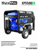
XP5500DX U S E R This manual provides information regarding the operation and maintenance of these products. We have made every effort to ensure the accuracy of the information in this manual. We reserve the right to change this product at any time without prior notice. M A N U A L 5800 Ontario Mills Pkwy Ontario, CA 91764 USA www.DuroMaxPower.
CONTENTS 1. Introduction Introduction ..................................................................................................................... 6 General Safety Procedures ............................................................................................ 8 Carbon Monoxide Safety.............................................................................................. 12 Unit and Purchase Information ..................................................................................
CONTENTS 6. Maintenance and Care Maintenance Schedule................................................................................................... 48 Maintenance Log ........................................................................................................... 49 Checking the Oil ............................................................................................................. 50 Changing the Oil..................................................................................
THE DUROMAX WAY The DuroMax Way is more than just a brand, it is our understanding and appreciation of just how important power can be to someone without it… DUROMAX FOR HOME Electricity in our home not only provides comfort but safety as well. From keeping the heat or A/C on to keeping our food cold, power is essential to our daily lives. Inevitability when disaster strikes and we are left without power for a prolonged period of time, our way of life is put at risk.
DuroMax Power Equipment is headquartered in Ontario, California and is the industry’s leader in Dual Fuel portable generator technology. In addition to a full assortment of portable generators ranging from digital inverters to large 15,000-watt portable standby units, our product line includes pressure washers, engines, pumps, and accessories. The foundation of our company is built on quality, reliability, durability, and customer service.
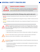
GENERAL SAFETY PROCEDURES SAFETY ALERT SYMBOL The safety alert symbol is used with one of the safety words (DANGER, CAUTION, or WARNING) to alert you of hazards. Please pay attention to these hazard notices both in this manual and on the generator. Please familiarize yourself with the following safety symbols and words: ● DANGER: Indicates a hazard that will result in serious injury or death if instructions are not followed.
GENERAL SAFETY PROCEDURES WARNING: This generator may emit highly flammable and explosive gasoline vapors, which can cause severe burns or even death. A nearby open flame can lead to an explosion even if not directly in contact with gasoline. ● Do not operate near an open flame. ● Do not smoke near the generator. ● Always operate on a firm, level surface. ● Always turn the generator off before refueling. ● Allow generator to cool for at least 2 minutes before removing the fuel cap.
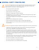
GENERAL SAFETY PROCEDURES In addition to the above safety notices, please familiarize yourself with the safety and hazard markings on the generator. DANGER 1.5” DO NOT OVERFILL THE GAS TANK OVERFILLING CAN RESULT IN A FIRE, EXPLOSION, OR DEATH.
GENERAL SAFETY PROCEDURES CAUTION HIGH TEMPERATURE DON’T TOUCH EXHAUST DANGER HOT KEEP SAFE DISTANCE BURN RISK CARBON MONOXIDE DON’T SAFE DISTANCE TOUCH 11
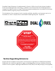
CARBON MONOXIDE SAFETY Carbon Monoxide Generators are convenient, but they can also be dangerous. All fuelburning appliances and equipment release a poisonous gas called carbon monoxide. Carbon monoxide (also known as CO) can be dangerous for humans and pets, even in small amounts, because it blocks oxygen from getting into your body. Carbon monoxide poisoning can lead to death in a very short time. It is odorless, tasteless and invisible, so you may be exposed without knowing it.
As the only safe way to use a portable generator, taking your generator outside is absolutely mandatory to keep your family safe from carbon monoxide. But there’s even more you can do. By educating yourself about all carbon monoxide risks, you’ll be better prepared to protect your family from this colorless, odorless threat. Visit takeyourgeneratoroutside.com for more information.
UNIT AND PURCHASE INFORMATION Serial Number Serial Number The serial number is located on the engine block, above and to the left of the oil fill. Serial number format The serial number will be shown in two parts. The engine model, followed by the serial number. Engine Model: _____________________________________________ Serial Number: _____________________________________________ STAPLE RECEIPT HERE A purchase receipt may be necessary for warranty parts or service in the future.
GENERATOR SETUP Proper setup of your generator will get you going as soon as possible while making sure you and your equipment are safe and cared for.
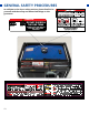
GENERATOR COMPONENTS 5. Fuel Tank 6. Power Panel 4. Fuel Valve 3. Choke Lever 7. Handles 8. Battery 2. Air Cleaner 1. Recoil Start 9. Oil Fill and Dipstick 1. Recoil Start – Easy pull recoil start to start the engine without the electric start. 2. Air Cleaner - A removable, cleanable, oiled, element that cleans the air going into the engine. 3. Choke Lever - Restricts the airflow into the carburetor to assist in starting the engine. 4.
13. Multimeter 12. Low Oil Alert 11. Engine Switch 10. Propane Inlet 19. Charging Light 14. Power Boost 16. GFCI 20A Receptacles 15. Circuit Breaker 18. CO Alert 17. 120/240V 4-Prong Twist Lock 13. Multimeter – Displays voltage, hertz, and time running. 14. Power Boost – DuroMax exclusive Power Boost doubles the amperage available in “120V Only” for heavy loads like RV air conditioners. 15. Circuit Breaker - Protects the panel from overload and short circuits. 16.
PACKAGE CONTENTS Your generator comes with the items listed below. Please check to see that all of the following items are included with your generator. Double-Sided Screw Driver Phillips and slot blade screwdriver used for generator maintenance. Oil Funnel w/ hose Used to add oil to the generator without messy spills. Spanner Spark Plug Wrench Assorted wrenches used in generator maintenance and assembly. 10mm/12mm and 13mm/15mm. Used in spark plug maintenance, inspection, and installation.
GENERATOR SETUP Step 1 - Remove Shipping Braces 1. Unpack a. Remove the generator from the box. b. Place the largest piece of packing foam on a flat surface. c. Flip the generator upside down on the pad. CAUTION: NEVER attempt this if you have put fuel or oil in the generator. 2. Remove braces The shipping braces prevent engine movement during shipment. Flip the generator over and remove the brightly colored braces between the motor and the frame, and the wood brace under the generator.
GENERATOR SETUP (CONTINUED) Step 2 - Wheel Kit Installation (Optional) 1. Install support legs a. Secure the support legs to the frame with the provided lock nuts. 2. Install wheel axle a. Insert wheel axle bolts through the frame and secure with the provided nut and wrenches 3. Install wheel axle bracket a. Insert wheel axle bracket bolts through the frame and secure with the provided nut and wrenches 4. Install inside wheel washers a.
5. Install wheels a. Place the wheels onto either side of the axle. 6. Install outside wheel washers a. Place the other large washers onto each side of the axle in front of the wheel. 7. Install cotter pins a. Place a cotter pin through the hole on each end of the axle and bend it out to secure the wheels. 8. Install handles a. Attach the handles to the brackets on the frame using the provided bolts and nuts. b. Flip the assembled generator over onto its wheels and support brackets.
GENERATOR SETUP (CONTINUED) Step 3 - Connect the Battery 1. Disconnected on arrival The generator battery is disconnected on arrival to prevent discharge or accidental starting in storage and transportation. 2. Locate the negative cable a. Locate the negative battery cable above and behind the battery. One side is connected to ground and the other end needs to be connected to the battery. b. Route the free end to the negative battery terminal. 3. Connect the negative cable a.
Step 4 - Adding Oil The generator requires engine oil to operate properly. The generator, when new from the package, contains no oil in the crankcase*. You must add the proper amount of oil before operating the generator for the first time. This amount is equal to the oil capacity of the engine crankcase: Model Number XP5500DX Engine Oil Capacity 20 fl. oz (0.6L) WARNING: Do not apply engine oils with additives or 2-stroke gasoline engine oils.
GENERATOR SETUP (CONTINUED) Step 5 - Adding Gasoline (Optional) Add Gasoline a. Make sure the generator is on a level surface. b. Unscrew gas cap and set aside (NOTE: the gas cap may be tight and hard to unscrew). c. Slowly add unleaded gasoline to the fuel tank. Be careful not to overfill. The fuel gauge on the top of the gas tank indicates how much gasoline is in the generator gas tank. d. Replace fuel cap and wipe up any spilled gasoline with a dry cloth.
Step 6 - Grounding the Generator Attach grounding wire a. Ground the generator by tightening the grounding nut against a grounding wire. b. Connect the other end to a copper or brass grounding rod that’s driven into the earth. A generally acceptable grounding wire is a No. 12 AWG (American Wire Gauge) stranded copper wire. Grounding codes can vary by location. Please contact a local electrician to check the grounding regulations for your area.
STARTING THE GENERATOR If this is not your first time using the generator, there are still steps you should take to prepare it for operation each time you use it. IMPORTANT: At this point, you should be familiar with the procedures described in the first portion of this section entitled “GENERATOR SETUP”. If you have not yet read this section, go back and read it now.
BEFORE YOU START YOUR GENERATOR Step 1 - Check the Oil Check the oil The generator is equipped with an automatic shutoff to protect it from damage due to low oil. Nonetheless, you should check the oil level of the engine before each use to ensure that the engine crankcase has a sufficient amount. To check the oil level: 28 a. Make sure the generator is on a level surface. b. Unscrew the oil filler/dipstick cap. c. With a dry cloth, wipe the oil off of the stick on the inside of the cap. d.
Step 2 - Check the Gas Level (Optional) Check fuel level If running the engine on gasoline, check to see that there is sufficient gasoline in the fuel tank. The fuel gauge on top of the tank will give a rough estimate of the gasoline level. The gauge will appear white then fill red as the tank is filled. Note: Fuel gauge may not register with less than 1/3 fuel tank full. DANGER 1.5” DO NOT OVERFILL THE GAS TANK OVERFILLING CAN RESULT IN A FIRE, EXPLOSION, OR DEATH.
STARTING THE GENERATOR Starting the Generator Using Gasoline 1. Shut breaker off The breaker is located on the right side of the front power panel. Flip the breaker down to prevent accidental load when starting the generator. 2. Turn gas valve on The gas valve is located above the recoil start on the bottom of the fuel tank. Rotate the valve counterclockwise to the vertical position to turn on the gas supply. 3. Close choke The choke lever is located above the air filter to the left of the recoil start.
5. Allow switch return to RUN When the engine starts, allow the engine switch to return to the “RUN” position. 6. Open choke Push the choke to the OPEN position as the engine warms up. CAUTION: LPG must be shut off when using gasoline! CAUTION: Gasoline must be shut off when using LPG! CAUTION: Disconnect all electrical loads from the generator before attempting to start! WARNING: Operating the starter motor for more than 5 seconds can damage the motor.
STARTING THE GENERATOR (CONTINUED) Starting the Generator Using Propane 1. Turn breaker off The breaker is located on the right side of the front power panel. Flip the breaker down to prevent accidental load when starting the generator. 2. Turn the gas valve off The gas valve is located above the recoil start on the bottom of the fuel tank. Rotate the valve clockwise to the horizontal position to stop the flow of gasoline to the carburetor. 3.
5. Close choke The choke lever is located above the air filter to the left of the recoil start. Slide the lever to the left to cut the air supply and allow more gas into the engine to start. 6. Start the generator The engine switch is located on the left side of the front power panel. Flip the switch up to the “START” position. When the engine starts, allow the engine switch to return to the “RUN” position. 7. Open choke Push the choke to the OPEN position as the engine warms up. 8.
STARTING THE GENERATOR (CONTINUED) Starting the Generator Using Propane WARNING: WHEN USING THE GENERATOR WITH LPG, MAKE SURE THERE IS NO POSSIBLE IGNITION SOURCE CLOSE TO THE GENERATOR. 1. Before using, make sure all of the LPG connectors and hoses are well connected and sealed. 2. Connect electrical devices to the generator ONLY after the engine runs smoothly. (There may be remnant gasoline in the carburetor; this can cause unsteady engine performance for several minutes) 3.
STARTING THE GENERATOR (CONTINUED) Starting the Generator Using Recoil Start 1. Shut breaker off The breaker is located on the right side of the front power panel. Flip the breaker down to prevent accidental load when starting the generator. 2. Select your fuel. If using gasoline, see step 2 on pg. 30. If using propane, see steps 2 - 4 on pg. 32. 3. Close choke The choke lever is located above the air filter to the left of the recoil start.
5. Pull the recoil start The recoil start is located on the left side panel next to the air filter. Pull the recoil handle slowly until resistance is felt, then quickly pull the recoil handle until fully extended. 6. Open choke After the engine has started, push the choke to the OPEN position as the engine warms up. 7. Turn breaker on and connect The breaker is located on the right side of the front power panel. Flip the breaker up to allow the power to flow to the receptacles.
USING THE GENERATOR If this is not your first time using the generator, there are still steps you should take to prepare it for operation each time you use it. IMPORTANT: At this point, you should be familiar with the procedures described in the first portion of this section entitled “GENERATOR SETUP”. If you have not yet read this section, go back and read it now.
USING THE GENERATOR AC Usage ● You may connect electrical devices running on AC current according to their wattage requirements. ● The chart below shows the rated and surge wattage of your generator according to its model number. ● The rated wattage corresponds to the maximum wattage the generator can output on a continuous basis. ● The surge wattage corresponds to the maximum amount of power the generator can output for a short period of time.
Tool or Appliance Rated (Running) Watts Additional Surge Watts Electric water heater (40 gal) 4000 0 Hot plate 2500 0 Radial arm saw 2000 2000 Electric stove 1500 0 Circular saw 1500 1500 Air compressor (1 HP) 1500 3000 Window air conditioner 1200 1800 Miter saw 1200 1800 Microwave 1000 2000 Well water pump 1000 1500 Reciprocating saw 960 1040 Sump pump 800 1200 Refrigerator freezer 800 1200 Furnace blower 800 1300 Computer 800 0 Electric drill 600 900 Tele
USING THE GENERATOR (CONTINUED) Connecting a Load to the Generator NOTE: Be sure to attach devices to the correct receptacle (outlet). ● 120V devices can be directly connected to the 120V ONLY receptacles. ● 120V devices can be connected to the 120/240V receptacle using an appropriate adapter. ● 240V devices can ONLY be connected to the 240V receptacle. CAUTION: Do not connect 50Hz or 3-phase loads to the generator. 1. Plug in devices Plug in devices to the appropriate receptacle.
Choosing the Right Power Cord Long or thin cords can drain the power provided to an electrical device by the generator. When using such cords, allow for a slightly higher rated wattage requirement for the electrical device. See the table below for recommended cords based on the power requirement of the electrical device. DEVICE REQUIREMENTS WIRE GAUGE BY LENGTH (ft.
USING THE GENERATOR (CONTINUED) Using the Digital Multimeter When the generator is started, the display will read the current voltage. Press the MODE button to cycle through the multimeter functions. 1. Voltage The voltage currently produced by the generator in volts. 2. Frequency The frequency currently produced by the generator in Hz. 3. Hours Run The number of hours the engine has currently been running.
4. Hours Total The number of hours the generator has been run in total.
MAINTENANCE AND CARE Proper maintenance and storage are essential to ensure trouble-free use of your generator when you need it. By following the maintenance and care requirements, you can keep your generator running smoothly and efficiently for years to come.
MAINTENANCE AND CARE Proper routine maintenance of your generator is essential for safe, economical, and trouble-free operation. It will also help reduce air pollution. WARNING: Improper maintenance, or failure to correct a problem before operation, can cause a malfunction in which you can be seriously injured or killed. Always follow the inspection, maintenance recommendations, and schedules in this instruction manual. ● Make sure the engine is off before you begin any maintenance or repairs.
MAINTENANCE LOG Date Generator Hours Maintenance Performed 49
MAINTENANCE AND CARE (CONTINUED) Checking the Oil Check the oil The generator is equipped with an automatic shutoff to protect it from damage due to low oil. Nonetheless, you should check the oil level of the engine before each use to ensure that the engine crankcase has a sufficient amount. To check the oil level: 50 a. Make sure the generator is on a level surface. b. Unscrew the oil filler/dipstick cap. c. With a dry cloth, wipe the oil off of the stick on the inside of the cap. d.
Changing the Oil Worn out or dirty oil does not cool the generator properly and can lead to catastrophic engine damage. In addition to regular oil changes, it is necessary to drain the oil from the crankcase if it has become contaminated with water or dirt. 1. Remove drain plug Using a 12 mm hex wrench, unscrew the oil drain plug, which is located on the crankcase underneath the oil filler/dipstick cap. Allow all the oil to drain from the generator. 2.
MAINTENANCE AND CARE (CONTINUED) Cleaning the Air Filter Routine maintenance of the air cleaner helps maintain proper airflow to the carburetor. Check that the air cleaner is free of excessive dirt after every use. Note: Improper maintenance may cause less air to enter the engine or dirty air to enter the engine causing overheating and engine wear. 1. Remove the filter cover screw Remove the filter cover screw. 2. Remove filter cover Remove the filter cover and the sponge-like element from the casing. 3.
4. Wash cleaner element Wash the sponge-like elements in household dish detergent and warm water. 5. Dry cleaner element Pat on a dry cloth and allow the elements to dry completely. 6. Add engine oil to elements Soak the dry elements in a small amount of engine oil. Wring out any excess oil. 7. Replace elements in casing Replace the sponge-like elements in the air cleaner casing. Attach the cover.
MAINTENANCE AND CARE (CONTINUED) Spark Plug Maintenance SPARK PLUG CONSULT MANUAL BEFORE REMOVING The spark plug is important for proper engine operation. A good spark plug should be intact, free of deposits, and properly gapped. Improper maintenance may cause reduced fuel economy, misfires, trouble starting, or damage to the spark plug threads. 1. Remove spark plug cap Pull on the spark plug cap to remove it. 2.
4. Replace if necessary If it is cracked or chipped, discard and replace it with a new spark plug. We recommend using an F7RTC spark plug such as NGK BP6ES. 5. Install spark plug Screw the spark plug back into its place on the generator using the spark plug wrench. 6. Replace spark plug cap Replace the spark plug cap.
MAINTENANCE AND CARE (CONTINUED) Storage and Transportation CAUTION: Never place any type of storage cover on the generator while it is still hot. When transporting your generator: ● Empty the gas tank (see “Emptying the Gas Tank” in the “Maintenance” section). ● Disconnect the spark plug. ● Do not obstruct any ventilation openings & keep the generator in a cool dry area. Storage Period Storage Preparation If you plan on starting the same day 1. 2. 3. 4. Turn off the main breaker.
SPECIFICATIONS AC Rated Wattage (Gasoline) 4500W AC Rated Wattage (Propane) 4275W AC Surge Wattage (Gasoline) 5500W AC Surge Wattage (Propane) 5225W AC Rated Voltage 120/240V AC Rated Frequency 60 Hz AC Phase Single Dimensions LENGTH 25in. WIDTH 23in. HEIGHT 22in. Engine Type 4-Stroke OHV Forced-Air Ignition System Non-Contact Transistor Displacement 224cc Starting Type Electric / Recoil Fuel Tank Capacity 4 US Gal. (15L) Oil Capacity 20 fl. oz. (0.
TROUBLESHOOTING This section of the manual is to help you troubleshoot problems with your generator.
TROUBLESHOOTING Problem The engine will not start Engine runs, but there is no electrical output The generator runs but does not support all electrical devices connected 60 Description Solution Engine switch is “OFF” Set engine switch to “RUN” Fuel Valve is “CLOSED” Turn the fuel valve to “OPEN” Choke is open Close the choke The engine is out of fuel Add fuel Fuel is old or contaminated Change fuel Spark plug is dirty Clean spark plug Spark plug is broken Replace spark plug The generato
Changing / Inspecting the Carbon Brushes The carbon brushes in conjunction with the AVR regulates power from the generator. The carbon brushes are wearable parts and should be inspected every 250 running hours. 1. Remove generator cover Remove the 2 bolts of the generator cover. Pull off the cover. 2. Remove bolt from brush Remove the bolt holding the carbon brush. 3. Disconnect AVR wires Remove the two wires from the AVR on the carbon brush.
TROUBLESHOOTING (CONTINUED) Changing / Inspecting the Carbon Brushes (Cont.) 4. Install new brush Install new carbon brush with bolt. 5. Connect AVR wires Insert and connect the 2 wires from the AVR, be sure to connect + and – correctly. 6. Replace generator cover Replace the back cover of the generator and secure it with the 2 bolts.
Changing / Inspecting the AVR The carbon brushes in conjunction with the AVR regulates power from the generator. If the generator is overheated or overloaded, the AVR may be damaged and require replacement. 1. Remove generator cover Remove the 2 bolts of the generator cover. Pull off the cover. 2. Remove AVR bolts Remove the 2 bolts holding the AVR. 3. Disconnect AVR wire clip Disconnect the wire clip.
TROUBLESHOOTING (CONTINUED) Changing / Inspecting the AVR (Continued) 4. Disconnect wires from brush Remove the 2 wires from the AVR on the carbon brush. 5. Install new AVR Install the new AVR with the 2 bolts. 6. Reconnect wires to brush Insert and connect the 2 wires from the AVR. Make sure to connect + and – correctly. 7. Reconnect the AVR wire clip Reconnect the wire clip.
8. Replace generator cover Replace the back cover of the generator and secure it with the 2 bolts.
WIRING DIAGRAM 66
WARRANTY 5-Year Warranty All DuroMax Power Equipment warrant the original purchasers to a 5-Year Parts Warranty (Residential Use ONLY: Unusually heavy or commercial use is covered for a period of 1 year) in the event of failure due to defects in electrical or mechanical components. Freight on any items submitted for replacement or repair under the warranty is the responsibility of the equipment owner. This warranty is non-transferable and only valid to the original purchaser.
maintenance listed in your owner’s manual. DuroMax Power Equipment recommends that you retain all receipts covering maintenance on your small off-road engine, but DuroMax Power Equipment cannot deny warranty solely for the lack of receipts or for your failure to ensure the performance of all scheduled maintenance.
WARRANTY (CONTINUED) Subsection (4) below. Any such part repaired or replaced under the warranty must be warranted for the remaining warranty period. (2) Any warranted part that is scheduled only for regular inspection in the written instructions required by subsection (d) must be warranted for the warranty period defined in Subsection (b) (2). A statement in such written instructions to the effect of “repair or replace as necessary” will not reduce the period of warranty coverage.
Exhaust Emission Warranty Parts List. (1) Fuel Metering System (i) Carburetor and internal parts (and/or pressure regulator or fuel injection system). (ii) Air/fuel ratio feedback and control system. (iii) Cold start enrichment system. (iv) Fuel tank. (2) Air induction system (i) Controlled hot air intake system. (ii) Intake manifolds. (iii) Air filter. (3) Ignition System (i) Spark Plugs. (ii) Magneto or electronic ignition system. (iii) Spark advance/retard system.
CUSTOMER SERVICE DuroMax Power Equipment is committed to ensuring that our products perform when they need to. Our generators are your lifeline in the event of an emergency. Should you have any problems, please contact our customer service department: DUROMAX POWER EQUIPMENT 5800 Ontario Mills Parkway Ontario, CA 91764 Customer Service: 844-DUROMAX Customer Service Hours: 8 am - 5 pm PT Website: www.DuroMaxPower.com Email: customerservice@DuroMaxPower.
5800 Ontario Mills Parkway Ontario, CA 91764 United States 844-DUROMAX REV: XP5500DX-08242021