
Service manual

2
8 Service Mode ----------------------------------------------------- 19
8.1. Cold-Start--------------------------------------------------- 19
8.2. Doctor Mode Table--------------------------------------- 20
8.3. Reliability Test Mode (CD Mechanism Unit)-------23
8.4. Self-Diagnostic Mode -----------------------------------24
8.5. Self-Diagnostic Error Code Table -------------------- 24
8.6. Sales Demonstration Lock Function ----------------25
9 Troubleshooting Guide---------------------------------------- 26
10 Disassembly and Assembly Instructions---------------27
10.1. Screw Types-----------------------------------------------27
10.2. Disassembly Flow Chart-------------------------------- 28
10.3. Main Components and P.C.B. Locations----------- 29
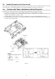
10.4. Disassembly of Top Cabinet--------------------------- 30
10.5. Disassembly of Front Panel Unit--------------------- 31
10.6. Disassembly of Panel P.C.B., LED P.C.B. and
Mic P.C.B. --------------------------------------------------32
10.7. Disassembly of Remote Sensor P.C.B.------------- 34
10.8. Disassembly of USB P.C.B. --------------------------- 35
10.9. Disassembly of CD Lid----------------------------------35
10.10. Disassembly of Rear Panel----------------------------36
10.11. Disassembly of Main P.C.B. ---------------------------37
10.12. Disassembly of Digital Amplifier IC (IC6000)------ 38
10.13. Disassembly of SMPS Module and Voltage
Selector P.C.B.--------------------------------------------39
10.14. Disassembly of CD Mechanism Unit ----------------40
10.15. Disassembly of CD Interface P.C.B.----------------- 41
10.16. Disassembly of Fan Unit ------------------------------- 42
11 Service Position ------------------------------------------------- 43
11.1. Checking of Panel P.C.B., LED P.C.B. and Mic
P.C.B.-------------------------------------------------------- 43
11.2. Checking of Main P.C.B. (Side B)--------------------43
11.3. Checking of Main P.C.B. (Side A)--------------------44
12 Block Diagram --------------------------------------------------- 45
12.1. Servo & System Control-------------------------------- 45
12.2. IC Terminal Chart----------------------------------------- 47
12.3. Audio --------------------------------------------------------48
12.4. Power Supply --------------------------------------------- 49
13 Wiring Connection Diagram---------------------------------51
14 Schematic Diagram---------------------------------------------53
14.1. Schematic Diagram Notes ----------------------------- 53
14.2. MAIN (CD Servo/Micon/Damp) Circuit ------------- 55
14.3. Panel Circuit----------------------------------------------- 63
14.4. USB, Music Port, Memory LED, Remote
Sensor & CD Interface Circuit ------------------------ 65
15 Printed Circuit Board ------------------------------------------66
15.1. Main P.C.B. ------------------------------------------------ 66
15.2. Panel, USB, Music Port & Memory LED
P.C.B.-------------------------------------------------------- 68
15.3. Remote Sensor & CD Interface P.C.B. ------------- 69
16 Appendix Information of Schematic Diagram ---------71
16.1. Voltage & Waveform Chart ---------------------------- 71
17 Exploded View and Replacement Parts List -----------77
17.1. Exploded View and Mechanical replacement
Part List----------------------------------------------------- 77
17.2. Electrical Replacement Part List ---------------------83