Serial and IR Automation Specifications and Programming Guide for iScan VP20, VP30, VP50 and VP50PRO Revised - December 2007
Document Contents 0 Preface......................................................................................................................... 3 0.1 Information Warranty Statement ........................................................................ 3 0.2 Document Scope and Limitations....................................................................... 4 0.3 Document Conventions....................................................................................... 4 0.3.1 Model Compatibility...
0 Preface Thank you for purchasing a DVDO iScan VPxx Series video processor. We believe the iScan will become a favorite device in your multimedia presentation system due to picture quality, ease of use, and the level of control the iScan gives you or your customer over the processed signal. This document is intended to cover the supplemental control functionality that is available for the iScan VP20, VP30, VP50, and VP50PRO. 0.
0.2 Document Scope and Limitations This document will cover the necessary information required to construct and transmit a serial (RS-232) or Infrared (IR) control signal to a DVDO iScan VPxx model video processor. These two basic mediums of control, are intended to convey the intentions of the user or automation system into the processes that operate the iScan.
0.3.2 Product Introduction This section is a brief introduction with pictures of each of the models of the iScan VPxx series – it is only intended as a brief “spotters guide” to iScan units. Please refer to your product’s user’s manual or our website for more in-depth product information at www.anchorbaytech.com/products/systems (replacement user’s manuals may be obtained in PDF form at the same website by clicking on the “support” tab and selecting “documentation”).
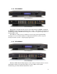
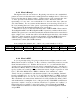
0.3.4 VP30 (MM603) iScan VP30 Front iScan VP30 Back This model is our high-end entry-level product with the full four HDMI complement, the RGBHV/Component 3 input and Analog video output – with available options like an SD-SDI input and the ABT102 Deinterlacing add-on card for exceptional reproduction of interlaced SD content.
0.3.6 VP50PRO (MM606) iScan VP50PRO Front iScan VP50PRO Back The iScan VP50PRO is the first Video Processor to achieve the THX certification for Video Processors, setting the benchmark for video processing. This device is also the first HDMI 1.
0.4 How does automation work? The iScan line of DVDO brand video processors are designed to enable control and flexibility over various input and output signal configurations – as well as our proprietary algorithms to improve several aspects of video quality and enable new capabilities that legacy devices by themselves are not able to achieve.
0.4.3 What is Binary? The digital world is all ones and zeros. By placing ones and zeros in a standardized pattern we can encode data that can be exchanged between multiple devices. The lowest level of encoding data is “binary notation”. In this notation, a “bit” represents the “true” or “false” presence of the numeric value at that bit location. Therefore, if the bit representing a “4” was “true”, one would add the “4” to the total of the “byte” (the total size of the number).
As an example, using “65” again – the HEX equivalent is “41h”. So what’s the “h” at the end? There are two commonly accepted ways to identify HEX notation in a sentence (or “string”). One is with the use of a “0x00” notation, where the two last zeros represent the two HEX characters, or with “00h” showing that this is a two nybble-byte in HEX notation. This can get confusing the more you learn – so take a moment to highlight this section or put a Post-It flag on this page for future reference. 0.4.
0.5 A brief dialog about remote controlling a VPxx series video processor Please be honest with yourself and ensure that you have understood the previous sections. If you’re not confident about how binary = HEX = decimal and relates to ASCII, then you may want to check out the internet for more information on digital information technology – or contact our Technical Support Hotline at (U.S. Domestic) 1866-423-3836 extension 333, or (International) 1-408-395-4455 extension 333.
0.6 A dialog about input video memories Due to the number of inputs and different types of input formats and ever further numerous types of source devices, we at Anchor Bay added input memories, which allow the user/system-integrator to configure very specific “effects” for a specific input format on a specific input connection. This means that a single input can have many different settings within the same control – just based on the input format that it is receiving.
This page intentionally left blank 13
1 RS-232 Control 1.1 The RS-232 Physical Connection RS-232 connections come in several styles which are accepted in the consumer electronics industry. The most common is the 9-pin D-Subminiature connector found on the back of most computers, and is the one that we use on the iScan VPxx products. The female serial port, found on the back panel of an iScan VPxx video processor. In this interface, there are a few different signals which must be supported.
1.1.1 The Anchor Bay RS-232 Protocol In this portion of the document, we will discus the three types of control communications that occur between the iScan and the controlling device. 1.1.2 A Dialog on Checksums Checksums are a way for a receiving device to double check the communication that occurred between the transmitting device and the receiver.
Also, each of the above “characters” has a related HEX notation number to go with it: “Attention” = Start Text or STX = 0x02 in HEX notation >>pause<< = Null or NUL = 0x00 in HEX notation “I’m Done Talking” = End Text or ETX = 0x03 in HEX notation It is up to the individual programmer to determine which method is easiest to understand – but if you haven’t chosen your programming style yet, this writer recommends sticking with HEX notation.
Before we start listing Command ID bytes, lets look at the “this long” portion of our sentence. For this, count the two command ID bytes (count the bytes, don’t add the values!), add the count of the two NUL bytes (again, don’t add the values), add the count of the value bytes (this really should sink in now - don’t add the values themselves). This equals the “byte-count” for the command sentence (string) – we are always counting bytes.
Let’s look at the sentence again, replacing what we know now: “0x02 0x33 0x30 0x30 0x35 0x41 0x31 0x00 0x31 0x00 [checksum – optional] 0x03” If you recall, unless your application calls for it specifically – YOU DO NOT NEED A CHECKSUM!!! If your application doesn’t need it, you are done with the sentence construction (just remove the optional placeholder for the “checksum - optional”): Let’s look at the sentence again, with out the optional checksum placeholder: “0x02 0x33 0x30 0x30 0x35 0x41 0x31 0x00 0x31
The checksum. This is the last part other than the Command ID Table and Value Table you might need to create a command string. Again, unless your customer/job requirements demand/specify it – YOU DO NOT NEED A CHECKSUM!! Assuming that you absolutely need to have a checksum due to a customer/job requirement, the checksum is fairly easy - add the value of every byte from the beginning of the string (at STX) to the last “NUL” just before the ETX (0x03).
1.2.
Preset 1 0x02 0x33 0x30 0x35 0x43 0x31 0x00 0x35 0x00 0x03 Preset 2 0x02 0x33 0x30 0x35 0x43 0x31 0x00 0x36 0x00 0x03 Preset 3 0x02 0x33 0x30 0x35 0x43 0x31 0x00 0x37 0x00 0x03 Preset 4 0x02 0x33 0x30 0x35 0x43 0x31 0x00 0x38 0x00 0x03 Preset 5 0x02 0x33 0x30 0x35 0x43 0x31 0x00 0x39 0x00 0x03 Preset 6 0x02 0x33 0x30 0x36 0x43 0x31 0x00 0x31 0x30 0x00 0x03 Preset 7 0x02 0x33 0x30 0x36 0x43 0x31 0x00 0x31 0x31 0x00 0x03 Preset 8 0x02 0x33 0x30 0x36 0x43 0x31 0x00 0x31 0x32 0x00 0x03 Preset 9 0x02 0x
Mosquito Noise Reduction Off 0x02 0x33 0x30 0x35 0x43 0x41 0x00 0x30 0x00 0x03 Level 1 0x02 0x33 0x30 0x35 0x43 0x41 0x00 0x31 0x00 0x03 Level 2 0x02 0x33 0x30 0x35 0x43 0x41 0x00 0x32 0x00 0x03 Level 3 0x02 0x33 0x30 0x35 0x43 0x41 0x00 0x33 0x00 0x03 Output Display Profile (recall – not save) Display Profile 1 0x02 0x33 0x30 0x35 0x45 0x30 0x00 0x31 0x00 0x03 Display Profile 2 0x02 0x33 0x30 0x35 0x45 0x30 0x00 0x32 0x00 0x03 Display Profile 3 0x02 0x33 0x30 0x35 0x45 0x30 0x00 0x33 0x00 0x03 Displ
1.3 Query Commands Query commands allow an external device to determine the setting of a given control. Building on the information presented in the previous section on constructing Command Packets, we will discuss the method for building a Query Packet. We’ll use the example of querying the “power” state of the unit (Command ID A1 used in the previous section).
1.4 Responses Responses (aka “feedback”) is arguably what really make RS-232 a powerful interface. As opposed to infrared control, the RS-232 port allows for bi-directional communication, so that the controlling device can get information from the controlled unit to make decisions based on the actual state of the unit. Response packets are about the same as Command or Query packets – with some minor differences is the data they contain.
Error “1” – Invalid checksum. This error means either the checksum you sent was wrong or the transmission was bad due to interference (double check your checksum calculation or your serial link). Error “2” – Invalid Incoming Packet ID (i.e. Command = “3”&”0”, Query = “2”&“0”, others are invalid when sent to the iScan) Error “3” – Invalid Setting (i.e. Power = “A”&”1”) if you get this error, make sure that the command is supported by the model you are using. Error “4” – Range Error (i.e.
The query response is the most involved response packet you will get in reply. This packet can have any data in the “value” bytes (although it will still be ASCII characters in HEX notation). Note that commands like “Model Name” will reply with text, while commands which are controlled by numbers will reply with numbers.
2 IR Control We have provided a reprint of Barry Gordon’s paper on IR interfacing in Appendix B at the end of this document. If you feel the information provided in the next few sections is a bit confusing, please take a moment to read that document. 2.1 The NEC IR Protocol (Factory Remote) In this section, we will provide the basic values needed for building a Pronto HEX compatible iScan factory remote control code.
2.2 The Anchor Bay IR Protocol (Discrete Control) As stated before, the discrete controls may be longer than the NEC protocol will allow. The NEC protocol only allows for one byte of “control/value” data to be transferred from the remote control to the controlled device.
If you recall from the RS-232 section, the command ID for the power control is “A” and “1”, but if you look at the Pronto HEX format, the command ID can only be one byte. This is why we made the Command IDs out of “HEX compatible” naming – so that the same data when represented as a byte will look very familiar. Thus the HEX byte for controlling power via IR is 0xA1.
This writer finds this to be the best step to explain the “bit burst” count in the Pronto HEX format. The bit burst is every “bit” from the after last “0000” in the header to the last “bit” in the command defenition. The bits being referred to are in bold and larger above. There is one start bit, 8 command ID bits, 8 value bits, 8 checksum bits, one stop bit, and an end of string bit. The bit count is then: 1 + 8 + 8 + 8 + 1 + 1 = 27.
2.2.
S-Video 2: 0000 006d 0024 0000 0156 00ab 0016 0015 0016 0015 0015 0040 0016 0015 0015 0015 0016 0015 0016 0015 0015 0040 0016 0015 0015 0015 0016 0015 0016 0015 0015 0015 0016 0040 0015 0015 0016 0015 0016 0015 0015 0015 0016 0040 0015 0015 0016 0015 0016 0015 0015 0015 0016 0015 0016 003f 0016 0040 0015 0015 0016 0040 0015 0040 0016 003f 0016 0040 0015 0040 0016 06c0 0156 0055 0016 00ab Component 1: 0000 006d 0024 0016 0015 0015 0016 0015 0016 0015 0015 0016 0156 0055 0016 0000 0156 00ab 0016 0015 0016 00
SDI: 0000 0016 0016 0016 0055 006d 0024 0000 0156 00ab 0016 0015 0016 0015 0015 0040 0016 0015 0015 0015 0016 0015 0015 0015 0040 0016 0015 0015 0015 0016 0015 0016 0015 0015 0015 0016 0040 0015 0015 0015 0016 0015 0015 0015 0016 0015 0016 0015 0015 0040 0016 0015 0015 0015 0016 0015 003f 0016 0040 0015 0040 0016 003f 0016 0015 0016 003f 0016 0040 0015 0040 0016 06c0 0156 0016 00ab Auto: 0000 006d 0016 0015 0016 0015 0016 0015 0156 0055 0024 0015 0016 0015 0016 0000 0156 00ab 0016 0015 0016 0015 0015 00
Right: 0000 006d 0016 0015 0016 0015 0016 0015 0055 0016 0024 0015 0016 0016 00ab 0000 0156 00ab 0016 0015 0016 0015 0015 0040 0016 0015 0015 0015 0016 0015 0040 0016 0015 0015 0015 0016 0015 0016 0015 0015 0015 0016 0040 0015 0015 003f 0016 0040 0015 0015 0016 0015 0016 003f 0016 0015 0016 0015 0015 0015 0015 0015 0040 0016 003f 0016 0015 0016 003f 0016 0040 0015 0040 0016 06c0 0156 Test Patterns On: 0000 0016 0016 0044 006c 001b 0000 0064 0064 0016 0015 0016 0015 0016 0015 0016 0015 0016 0015 0016 004
Cue Off: 0000 0016 0016 0044 006c 001b 0000 0064 0064 0016 0015 0016 0015 0016 0015 0016 0041 0016 0015 0016 0041 0015 0016 0015 0016 0015 0016 0015 0016 0015 0016 0015 0016 0041 0016 0041 0016 0015 0015 0016 0015 0016 0015 0016 0015 0016 0041 0016 0041 0016 0015 0016 0041 0016 0015 0044 016 0001 On: 0000 0016 0016 0044 006c 001b 0000 0064 00640016 0015 0016 0015 0016 0015 0016 0041 0016 0015 0016 0041 0015 0016 0015 0016 0041 0016 0015 0016 0015 0016 0015 0016 0041 0016 0041 0016 0015 0015 0016 0041 001
IAR Preset 1: 0000 006c 001b 0000 0064 0064 0016 0041 0016 0015 0016 0015 0016 0015 0016 0015 0016 0041 0016 0041 0016 0041 0016 0015 0016 0015 0016 0041 0016 0015 0016 0041 0016 0041 0016 0015 0016 0015 0016 0041 0016 0015 0016 0041 0016 0015 0016 0041 0016 0015 0016 0015 0016 0015 0044 0044 0016 0001 IAR Preset 2: 0000 006c 001b 0000 0064 0064 0016 0041 0016 0015 0016 0015 0016 0015 0016 0015 0016 0041 0016 0041 0016 0041 0016 0041 0016 0015 0016 0041 0016 0015 0016 0041 0016 0041 0016 0015 0016 0015 0016
1.55:1 0000 006c 001b 0000 0064 0064 0016 0015 0016 0015 0016 0015 0016 0015 0016 0041 0016 0015 0016 0041 0016 0015 0016 0015 0016 0041 0016 0015 0016 0015 0016 0041 0016 0041 0016 0015 0016 0015 0016 0015 0016 0041 0016 0015 0016 0015 0016 0015 0016 0015 0016 0015 0016 0041 0044 0044 0016 0001 1.
Audio 4: 0000 006c 001b 0000 0064 0064 0016 0015 0016 0041 0016 0015 0016 0041 0016 0015 0016 0015 0016 0041 0016 0015 0016 0015 0016 0015 0016 0041 0016 0015 0016 0041 0016 0041 0016 0015 0016 0015 0016 0015 0016 0041 0016 0041 0016 0041 0016 0041 0016 0041 0016 0041 0016 0015 0044 0044 0016 0001 Analog: 0000 006c 001b 0000 0064 0064 0016 0015 0016 0041 0016 0015 0016 0041 0016 0015 0016 0015 0016 0041 0016 0015 0016 0041 0016 0015 0016 0041 0016 0015 0016 0041 0016 0041 0016 0015 0016 0015 0016 0041 0016
On: 0000 0016 0016 0044 006c 001b 0000 0064 0064 0016 0041 0016 0041 0016 0041 0016 0015 0016 0015 0016 0041 0041 0016 0041 0016 0041 0016 0015 0016 0015 0016 0015 0016 0041 0016 0041 0016 0015 0015 0016 0015 0016 0015 0016 0015 0016 0041 0016 0041 0016 0015 0016 0015 0016 0015 0044 0016 0001 Deinterlacing Modes Auto: 0000 006c 001b 0000 0064 0064 0016 0041 0016 0015 0016 0015 0016 0041 0016 0015 0016 0015 0016 0041 0016 0015 0016 0015 0016 0041 0016 0041 0016 0015 0016 0041 0016 0041 0016 0015 0016 0015
Curtain: 0000 006d 0024 0000 0156 00ab 0016 0015 0016 0015 0015 0040 0016 0015 0015 0015 0016 0015 0016 0015 0015 0040 0016 0015 0015 0015 0016 0015 0016 0015 0015 0015 0016 0040 0015 0015 0016 0015 0016 0015 0015 0015 0016 0015 0016 003f 0016 0015 0016 0015 0015 0015 0016 0015 0016 003f 0016 0040 0015 0040 0016 0015 0015 0040 0016 003f 0016 0040 0015 0040 0016 06c1 0156 0055 0016 00ab 4:3 0000 0016 0016 0016 0156 006c 0024 0000 0156 00ac 0016 0015 0016 0015 0015 0040 0016 0015 0015 0015 0016 0015 0015 001
Viewing Modes: 0000 006c 0024 0000 0156 00ac 0016 0015 0016 0015 0015 0040 0016 0015 0015 0015 0016 0015 0016 0015 0015 0041 0016 0015 0015 0015 0016 0015 0016 0015 0015 0015 0016 0041 0015 0015 0016 0015 0016 0040 0016 0015 0016 0015 0015 0015 0016 0040 0015 0015 0016 0041 0015 0015 0016 0015 0016 0040 0016 0041 0015 0041 0016 0015 0015 0040 0016 0015 0015 0041 0016 06cf 0156 0056 0016 00ac Output Setup: 0000 006c 0024 0000 0156 00ac 0016 0015 0016 0015 0015 0040 0016 0015 0015 0015 0016 0015 0016 0015 001
3 Automation Command IDs and Values This section beginning on the next page, contains the entire list of Control/Query commands available with the iScan VPxx line of video processors. The two character Command ID is in bold-underline (example: A1 for “Power”). The possible values are given for each control in bold (example: 1.000). We have presented the list in the same layout as the OSD starting on the next page, to allow for quick location of the control you are seeking.
Complete OSD Menu Tree Input Select – 4C Video 1 - 1 Video 2 - 2 S-Video 1 - 3 S-Video 2 - 4 Component 1 - 5 Component 2 - 6 RGBHV/Component - 7 HDMI 1 - 8 HDMI 2 - 9 HDMI 3 - 10 HDMI 4 - 11 SD/HD-SDI 1 - 12 (with SD/HD-SDI module installed) (with HD-SDI module installed) SD/HD-SDI 2 - 14 Auto - 13 Input Aspect Ratio (OSD MENU ONLY) Frame AR – 4E 4:3 - 1 16:9 - 2 Active AR – 50 1.33:1 - 1 1.55:1 - 2 1.66:1 - 3 1.78:1 - 4 1.85:1 - 5 2.
Borders (see below) Horizontal – 44 Range: 0-200 Vertical – 45 Range: 0-200 Preset – E1 4:3 Full Frame - 1 Letterbox - 2 16:9 Full Frame - 3 4:3 Stretch - 14 Preset 1 - 4 Preset 2 - 5 Preset 3 - 6 Preset 4 - 7 Preset 5 - 8 Preset 6 - 9 Preset 7 - 10 Preset 8 - 11 Preset 9 - 12 Preset 10 - 13 User - 0 (there is no safety for this function) Save User to – 53 Preset 1 - 1 Preset 2 - 2 Preset 3 - 3 Preset 4 - 4 Preset 5 - 5 Preset 6 - 6 Preset 7 - 7 Preset 8 - 8 Preset 9 - 9 Preset 10 - 10 Input Adjust (OSD MEN
Deinterlacing – 49 Auto - 6 Film Bias Mode - 0 Video Mode - 1 Forced 3:2 Mode - 8 Forced 2:2 Mode - 10 2:2 Even Mode - 2 2:2 Odd Mode - 3 Game Mode 1 - 4 Game Mode 2 - 5 Field-Scale - 9 PReP – B6 Off - 0 On - 1 Cadence Detect – BB Off - 0 On - 1 Pass Through – A7 Off - 0 On - 1 Overscan – 46 Range: 0-20 Image Shift (see below) Horizontal - 54 Range: 0-30 Vertical – 47 Range: 0-50 Color Space – 87 RGB - 1 YPbPr - 2 YCbCr 4:2:2 - 3 YCbCr 4:4:4 - 4 Auto - 5 Input Level – F0 Video - 1 PC - 2 VCR Mode – 48 Off -
Auto AR – B0 Off - 0 On - 1 Auto Color Space – B1 Off - 0 On - 1 Auto Priority – 81 Range: 1-13 Audio Input – 4A Audio 1 - 1 Audio 2 - 2 Audio 3 - 3 Audio 4 - 4 Stereo - 5 HDMI - 6 Off - 0 AV Lipsync – 4B Range: 0-200 Picture Control (OSD MENU ONLY) Fine Detail – C8 Range: (-100)-(+100) Edge Enhancement – C9 Range: (-100)-(+100) Brightness – 21 Range: (-100)-(+100) Contrast – 22 Range: (-100)-(+100) Saturation – 23 Range: (-100)-(+100) Hue – 24 Range: (-100)-(+100) Y/C Delay – 27 Range: (-100)-(+100) CUE Co
Configuration (OSD MENU ONLY) Test Patterns – 80 Off - 0 Frame Geometry - 1 Brightness/Contrast - 2 Checker board - 3 Vertical Lines - 4 Horizontal Lines - 5 Judder - 6 Color8 Bars75 - 7 Color8 Bars100 - 8 Window IRE10 - 9 Window IRE20 - 10 Window IRE30 - 11 Window IRE40 - 12 Window IRE50 - 13 Window IRE60 - 14 Window IRE70 - 15 Window IRE80 - 16 Window IRE90 - 17 Window IRE100 - 18 Gray Ramp - 19 XHatch Coarse - 20 XHatch Fine - 21 Focus - 22 Half B/W - 23 H-Clr7 Bars75 - 24 H-Clr7 Bars100 - 25 H-Clr8 Bars
User Mode – 85 Normal - 1 Advanced - 2 (Unit will reply with acknowledge, then switch to new baud-rate) Serial Port Rate – A3 4800bps - 1 9600bps - 2 14400bps - 3 19200bps - 4 38400bps - 5 57600bps - 6 (Use value “0” – there is no safety for this function) Factory Default – AC (Use value “0” – there is no safety for this function) Software Update – AD 12V Trigger Levels (OSD MENU ONLY) Trigger #1 – B8 Normal - 1 Negative - 2 Trigger #2 – B9 Normal - 1 Negative - 2 Information – A5 Off - 0 On - 1 Output Setu
1365x768 - 35 852x576 - 15 1366x768 (1) - 16 1366x768 (2) - 33 1360x768 (1) - 31 1360x768 (2) - 32 1280x768 - 17 1024x1024 - 18 1024x852 - 19 1024x768 - 36 1024x576 - 20 848x600 - 21 1365x1024 - 22 1400x1050 - 23 1400x788 - 24 960x540 - 25 1280x960 - 26 1440x960 - 27 1440x1152 - 28 User - 29 USER RESOLUTION CONTROLS: Horizontal Shift (OSD MENU ONLY, SET FRONT PORCH AND BACK PORCH) Horizontal Size – 62 Range: 640-2000 (Limited Pixel clock, must not exceed 180MHz) Horizontal Front Porch – 63 Range: 0-512 (See
Aspect Ratio (OSD MENU ONLY) Display – 6A 4:3 - 1 5:4 - 2 16:9 - 3 2.35:1 - 4 User - 5 Display User Value – 88 Range: 1.00-3.00 Lens – B7 Mode 1 - 1 Mode 1 “Auto” - 2 Mode 2 - 3 None - 0 Screen – 89 4:3 - 1 5:4 - 2 16:9 - 3 2.35:1 - 4 User - 5 Screen User Value – 8A Range: 1.00-3.
Output Level – E6 Video - 1 PC - 2 Framerate (OSD MENU ONLY) When input is: 24Hz - NOT YET DEFINED 24Hz Lock - 1 48Hz Lock - 2 60Hz Lock - 3 72Hz Lock - 4 Unlock - 0 24Hz input, Unlocked output framerate – NOT YET DEFINED Range: 24.00-80.00 When input is: 25Hz - NOT YET DEFINED 25Hz Lock - 1 50Hz Lock - 2 75Hz Lock - 3 Unlock - 0 25Hz input, Unlocked output framerate – NOT YET DEFINED Range: 24.00-80.
Border Level – 4F Range: (-16)-(+100) Output Picture Controls (OSD MENU ONLY) Presets – C4 ISF Day Normal - 1 ISF Day Bright - 2 ISF Night - 3 Preset 1 - 4 Preset 2 - 5 Brightness – C0 Range: (-100)-(+100) Contrast – C1 Range: (-100)-(+100) Saturation – C2 Range: (-100)-(+100) Hue – C3 Range: (-100)-(+100) HDCP Mode - EA Off - 0 On - 1 12V Trigger #2 – C7 Lens - 2 On - 1 Off - 0 Audio Select - BA S/PDIF - 1 HDMI - 2 Display Profile (OSD MENU ONLY) Select – E0 Profile 1 - 1 Profile 2 - 2 Profile 3 - 3 Profil
Appendix A. Decimal to Binary to HEX to ASCII Conversion Table Some ASCII Characters will not be used ever in the iScan communication – these are grayed out for clarity (the entire list is published for the sake of completion).
39 40 41 42 43 44 45 46 47 48 49 50 51 52 53 54 55 56 57 58 59 60 61 62 63 64 65 66 67 68 69 70 71 72 73 74 75 76 77 78 79 80 81 82 83 0010 0111 0010 1000 0010 1001 0010 1010 0010 1011 0010 1100 0010 1101 0010 1110 0010 1111 0011 0000 0011 0001 0011 0010 0011 0011 0011 0100 0011 0101 0011 0110 0011 0111 0011 1000 0011 1001 0011 1010 0011 1011 0011 1100 0011 1101 0011 1110 0011 1111 0100 0000 0100 0001 0100 0010 0100 0011 0100 0100 0100 0101 0100 0110 0100 0111 0100 1000 0100 1001 0100 1010 0100 1011 0100 1
84 85 86 87 88 89 90 91 92 93 94 95 96 97 98 99 100 101 102 103 104 105 106 107 108 109 110 111 112 113 114 115 116 117 118 119 120 121 122 123 124 125 126 127 128 0101 0100 0101 0101 0101 0110 0101 0111 0101 1000 0101 1001 0101 1010 0101 1011 0101 1100 0101 1101 0101 1110 0101 1111 0110 0000 0110 0001 0110 0010 0110 0011 0110 0100 0110 0101 0110 0110 0110 0111 0110 1000 0110 1001 0110 1010 0110 1011 0110 1100 0110 1101 0110 1110 0110 1111 0111 0000 0111 0001 0111 0010 0111 0011 0111 0100 0111 0101 0111 01
129 130 131 132 133 134 135 136 137 138 139 140 141 142 143 144 145 146 147 148 149 150 151 152 153 154 155 156 157 158 159 160 161 162 163 164 165 166 167 168 169 170 171 172 173 1000 0001 1000 0010 1000 0011 1000 0100 1000 0101 1000 0110 1000 0111 1000 1000 1000 1001 1000 1010 1000 1011 1000 1100 1000 1101 1000 1110 1000 1111 1001 0000 1001 0001 1001 0010 1001 0011 1001 0100 1001 0101 1001 0110 1001 0111 1001 1000 1001 1001 1001 1010 1001 1011 1001 1100 1001 1101 1001 1110 1001 1111 1010 0000 1010 0001 1
174 175 176 177 178 179 180 181 182 183 184 185 186 187 188 189 190 191 192 193 194 195 196 197 198 199 200 201 202 203 204 205 206 207 208 209 210 211 212 213 214 215 216 217 218 1010 1110 1010 1111 1011 0000 1011 0001 1011 0010 1011 0011 1011 0100 1011 0101 1011 0110 1011 0111 1011 1000 1011 1001 1011 1010 1011 1011 1011 1100 1011 1101 1011 1110 1011 1111 1100 0000 1100 0001 1100 0010 1100 0011 1100 0100 1100 0101 1100 0110 1100 0111 1100 1000 1100 1001 1100 1010 1100 1011 1100 1100 1100 1101 1100 1110 1
219 220 221 222 223 224 225 226 227 228 229 230 231 232 233 234 235 236 237 238 239 240 241 242 243 244 245 246 247 248 249 250 251 252 253 254 255 1101 1011 1101 1100 1101 1101 1101 1110 1101 1111 1110 0000 1110 0001 1110 0010 1110 0011 1110 0100 1110 0101 1110 0110 1110 0111 1110 1000 1110 1001 1110 1010 1110 1011 1110 1100 1110 1101 1110 1110 1110 1111 1111 0000 1111 0001 1111 0010 1111 0011 1111 0100 1111 0101 1111 0110 1111 0111 1111 1000 1111 1001 1111 1010 1111 1011 1111 1100 1111 1101 1111 1110 111
Appendix B. Infrared Control White Paper by Barry Gordon Note: This article in Sections 2.1 through 2.5 is reprinted with permission from Barry Gordon. The original article was printed circa 1998, although the information it contains is still very pertinent. We wish to thank Barry for allowing us to reprint the article. Anchor Bay is not responsible for the information presented within the below article.
been pressed (and perhaps even what device this key is for). We first need to simplify the problem so that we don’t have deal with too many "Pulse widths". We can easily do this by representing the number in base 2, or binary. (I apologize if this now gets a little technical, but in reality it already has). In binary there are only two digits to worry about not ten as in decimal. Therefore we only need to have two distinct "pulse widths".
having them equal. We might choose 48,24 for the "1" and 24,24 for the "0". In fact this is what Sony has done in its IR remotes. [Note: If you work through the numbers you will find that Sony IR signaling uses a sequence of 1200 microseconds of light followed by 600 microseconds of no light to represent a "1"; and a sequence of 600 microseconds of light followed by 600 microseconds of no light to represent a "0"]. In general all IR equipment is forgiving and operates with in a timing tolerance of +/- 10%.
A Burst Pair Sequence usually looks as follows: Lead in Burst Pair Data Burst Pairs Lead Out Burst Pair The Lead In Burst pair can be thought of as the hello or wake up burst. It tells the receiver to start listening (or rather looking) very closely as what is coming. It is usually of different timing duration than the Burst Pairs in the data part. Technically it is also used to set the receivers AGC level, a factor related to how much the receiver will amplify the IR light it sees.
IR Codes The world of IR remotes has become a commodity world. IR remotes (simple ones, not the Pronto) are relatively inexpensive. I bought 5, credit card sized, universal remotes for $10. They are three times as thick as a credit card but the same height and width. Fits nicely in a shirt pocket. (A true couch potato must NEVER EVER be without a remote!). This has happened because there has been a large degree of standardization on the chips that generate the IR codes and receive them.
Let us break it up to decipher it. Preamble 0000 0067 000 0015 Word 1 0 so it is a learned IR code Word 2 103 decimal which when plugged into the formula already given yields an IR Carrier frequency of about 40kHz. Word 3 0000 is the length of the One Time Burst. There is no one time burst Word 4 Decimal 21 is the length of the repeat burst. There are 21 bits (Burst pairs) in this code. The code length is 20 bits plus 1 more pair for the Lead in.
Continuing on to the device code we have: Word 21,22 0018 0018 (24,24 decimal) Burst Pair 8, bit 1 = "0" Word 23,24 0030 0018 (48,24 decimal) Burst Pair 9, bit 2 = "1" Word 25,26 0018 0018 (24,24 decimal) Burst Pair 10, bit 3 = "0" Word 27,28 0030 0018 (48,24 decimal) Burst Pair 11, bit 4 = "1" Word 29,30 0030 0018 (48,24 decimal) Burst Pair 12, bit 5 = "1" Word 31,32 0030 0018 (48,24 decimal) Burst Pair 13, bit 6 = "1" Word 33,34 0018 0018 (24,24 decimal) Burst Pair 14, bit 7 = "0" Word 35,36
NEC IR Code Format Parameter Carrier Frequency Unit of Burst Time Lead In Burst "1" Burst Pattern "0" Burst Pattern Lead Out Decimal Value 40kHz 22 cycles of the carrier 341 171 22 96 22 24 22, 1427 HEX Value 0156 00ab 0016 0060 0016 0016 0016 0593 Doing the arithmetic we see that this code uses a base time of 550 microseconds. The lead in is a unique burst as is the lead out.
If you work out all of the detailed analysis in a manner similar to that shown for the Sony you should determine that the carrier frequency is indeed 40kHz, there are 34 total burst pairs in the one burst sequence used, and the burst sequence is repeatable. The actual 32 bits of data is: 00010101 11101010 01011000 10100111 Looking at the adjacent fields (1 & 2, 3 & 4) we see they are compliments of each other. A short way of checking for compliments is that ones become zeros and zeros become ones.
Appendix C. Help and Support Thanks for taking the time to read this document. We have tried to cover in easy-tounderstand terms, every facet of automation the iScan supports – while attempting at answer every question we’ve ever been asked by customers and installers. However – if after reading this document you have questions which are left unanswered, please call or email us to get an answer. We are located in California (U.