
User Manual
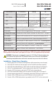
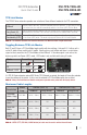

1. Status Indicator LEDs Lit Continuously Blinking Off
HDCP HDCP-encrypted video
signal transmission
—
No HDCP encryption
VIDEO SIGNAL Video signal transmission
—
No video signal
transmission
LINK TPS connection detected and
HDBaseT or LR Link Mode
TPS connection detected
and LPPF Link Mode
(1)
TPS connection failed
between TX and RX
LIVE
—
Device powered and
ready to use
No power supply
present or malfunction
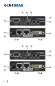
2. NORMAL / PROG
Set the RS-232 switch to the NORMAL position. The PROG position is only
for use by qualied technical personnel.
3. LR / AUTO Use these switches to toggle between TPS link modes - see page 5.
4. Remote PWR Jumper A remote power settings jumper is located on the side of the unit - see page 4.
5. IR IN/OUT Connect the IR Transmitter to IR OUT. Connect the IR Receiver to IR IN.
6. DVI IN/OUT Connect the source device to DVI IN. Connect the display to DVI OUT.
7. TPS IN/OUT Use a high quality TP cable to connect TPS OUT to TPS IN - see warning below.
8. Ethernet IN/OUT Connect to Ethernet switch and/or devices - see warning below.
9. 12 VDC IN Connect AC Power Adapter to TX and/or RX. Settings vary - see page 4.
10. RS-232 IN/OUT Connect to Ethernet switch and/or devices - see Installation.
Note 1: These units enter Low Power Partial Functionality (LPPF) Mode when no signal is detected on the input.
Normal operation is restored when a signal appears on the input. LPPF is not supported with Long Reach Mode.
WARNING: Ethernet ports are designed to connect to 10/100 BaseT Ethernet products only.
Do not connect any device to the TPS connector unless you are sure they are compatible.
Connecting incompatible devices with similar connectors may cause harm to the devices.
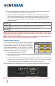
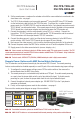
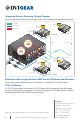
Installation: Stand-Alone Operation
1. Remove power from all devices (installing devices while powered may cause damage).
2. Set the RS-232 switches on the front panels of the TX and RX to the Normal position.
3. Set the TPS link mode with the LR / AUTO switch on the front of the units (see page 5).
4. Set the TX remote power mode
(2)
with the jumper on the side of the TX (see page 4).
5. Connect a CAT-X twisted pair cable to the TPS OUT on the transmitter unit.
6. Set the RX remote power mode
(2)
with the jumper on the side of the RX (see page 4).
7. Connect the other end of the CAT-X twisted pair cable to the TPS IN on the receiver unit.
8. Connect a DVI or HDMI signal source to the DVI IN port on the transmitter unit.
9. Connect a DVI or HDMI display device (e.g. projector) to the DVI OUT on the receiver unit.
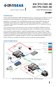
DVI-TPS-TX95-HD
DVI-TPS-RX95-HD
DVI TPS Extender
Quick Start Guide
3